OLED ink-jet printing method and device
An inkjet printing device and inkjet printing technology, applied in the field of OLED printing, can solve the problems of very demanding processor processing capacity, extremely high camera resolution requirements, and long information processing time, so as to avoid missed detection, The effect of convenient calculation and less variables
- Summary
- Abstract
- Description
- Claims
- Application Information
AI Technical Summary
Problems solved by technology
Method used
Image
Examples
Embodiment 1
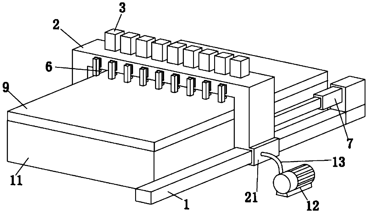
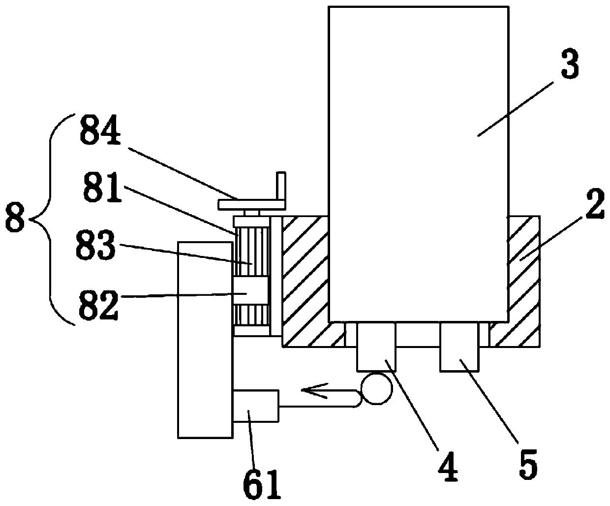
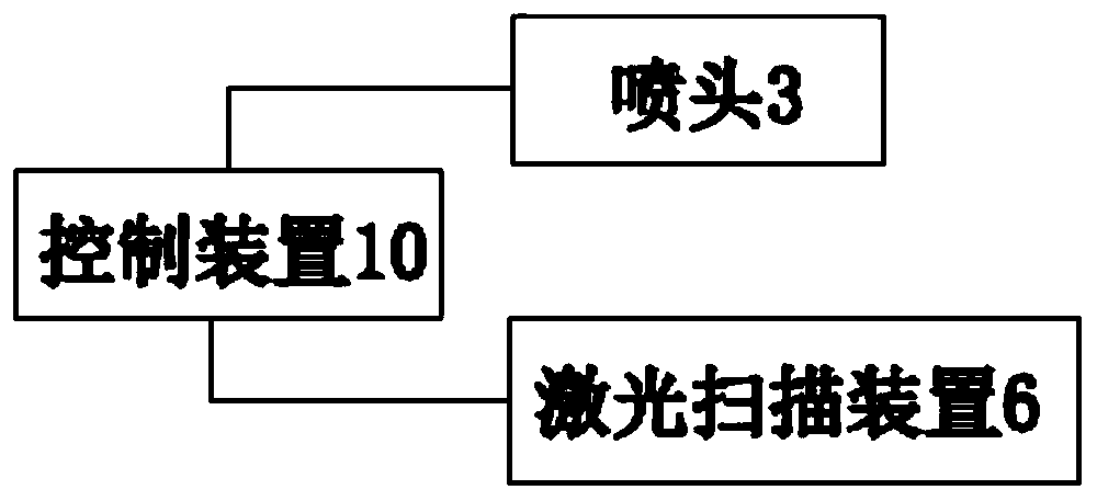
[0031] The specific embodiment of the present invention is as Figure 1-4 As shown, an OLED inkjet printing method, when a plurality of nozzles 3 arranged in a single row and reciprocating along a straight line spray ink to an OLED substrate 9, the ink droplets 9 of the main nozzles 4 located on the nozzles 3 are detected by laser scanning Check whether it is dripping normally, and use the re-spray nozzle 5 on the nozzle 3 to immediately re-spray the missing or less sprayed part of the OLED substrate 9 .
[0032] During laser scanning, the direction of the laser light irradiated on the ink droplet 9 is perpendicular to the drop direction of the ink droplet 9 . The arrangement direction of the laser corresponds to the arrangement direction of each main nozzle 4 , and the irradiation height of the laser corresponds to the ink droplet 9 on the main nozzle 4 in the initial stage of dropping. The laser emitting end and receiving end of the laser move synchronously with the single ...
Embodiment 2
[0040] Such as Figure 5 As shown, the difference from Embodiment 1 is that the laser scanning device 6 includes a laser transmitter receiver 61 and a reflective mirror 62 sequentially arranged along the optical path. The laser transmitter receiver 61 is fixedly connected with the reflector 62 . The laser emitting end of the laser emitting receiver 61 faces downward. The reflector 62 is located below the laser emitting end of the laser emitting receiver 61 and is arranged obliquely relative thereto. In this embodiment, the laser emitting end of the laser transmitting receiver 61 is vertically downward, and the inclination angle of the reflecting mirror 62 relative to the horizontal plane is 45°. The laser light reflected by the mirror 62 is irradiated in the horizontal direction.
[0041] In addition to the above embodiments, the main nozzle 4 and the supplementary spray nozzle 5 can also be respectively arranged on two different spray heads 3 .
PUM
 Abstract
Description
Claims
Application Information
 - R&D Engineer
- R&D Manager
- IP Professional
- Industry Leading Data Capabilities
- Powerful AI technology
- Patent DNA Extraction
Browse by: Latest US Patents, China's latest patents, Technical Efficacy Thesaurus, Application Domain, Technology Topic, Popular Technical Reports.
© 2024 PatSnap. All rights reserved.Legal|Privacy policy|Modern Slavery Act Transparency Statement|Sitemap|About US| Contact US: help@patsnap.com


