Coupling beam damper based on magneto-rheological elastomer material

A magnetorheological elastomer and magnetorheological elasticity technology, applied in the direction of joists, girders, truss beams, etc., can solve the problems of high engineering cost, small control range, and easy resonance, so as to improve the ability to resist horizontal loads , Wide tuning range and small footprint

Active Publication Date: 2020-02-07
WUHAN UNIV OF TECH
View PDF7 Cites 3 Cited by
  • Summary
  • Abstract
  • Description
  • Claims
  • Application Information

AI Technical Summary

Problems solved by technology

The existing damping structure can be divided into passive control and semi-active control. Passive control has the advantages of low cost and clear vibration reduction mechanism, but the control range is small, and resonance is prone to occur during the vibration reduction process; The control force can greatly reduce the vibration response of the structure, but it needs to consume a huge amount of external energy, resulting in high engineering cost, and the control device may enter the paralyzed state before the structure during the earthquake
[0006] Most of the current coupling beam dampers are passively controlled. Adding a mild steel damper to the coupling beam can effectively reduce the earthquake effect, and it is easy to repair and replace after the earthquake. However, the mild steel material can only play a role after entering the plastic state. , can not reduce the effect of wind vibration, affecting the human comfort of high floors
Although the viscoelastic damper made of rubber material has good resistance to wind vibration and earthquake, it will still resonate in a certain frequency of earthquake and cause more serious damage. Therefore, it is necessary to improve the existing technology. Improve

Method used


Image

  • Coupling beam damper based on magneto-rheological elastomer material
  • Coupling beam damper based on magneto-rheological elastomer material
  • Coupling beam damper based on magneto-rheological elastomer material

Examples


Embodiment Construction

[0028] In order to better understand the present invention, the present invention will be further described below in conjunction with the accompanying drawings and specific embodiments.

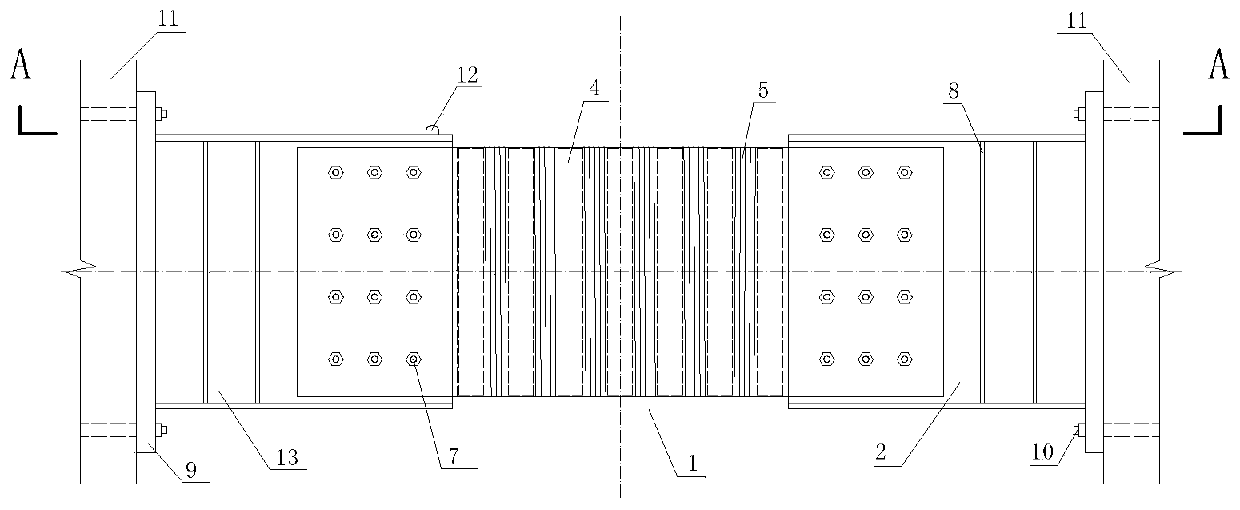
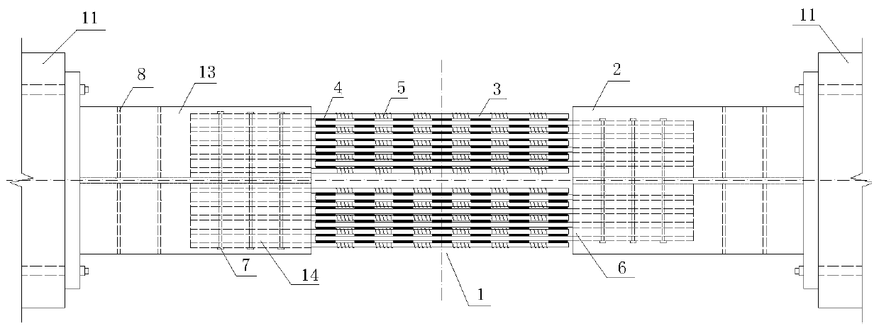
[0029] like figure 1 and figure 2 A coupling beam damper based on a magnetorheological elastomer material as shown, including a first H-shaped steel 13 and a second H-shaped steel 2, and a damping device for connecting the first H-shaped steel 13 and the second H-shaped steel 2 1; Specifically, the inner end of the first H-shaped steel 13 / second H-shaped steel 2 is connected to the shock absorbing device 1, and the outer end of the first H-shaped steel 13 / second H-shaped steel 2 is connected to the shear force through the gusset plate 9 respectively. Wall 11 is connected. In this embodiment, the outer ends of the first H-shaped steel 13 and the second H-shaped steel 2 are respectively welded and fixed to one side of the gusset plate 9, and the gusset plate 9 is connected to the shear wall ...


PUM

PropertyMeasurementUnit
lengthaaaaaaaaaa
thicknessaaaaaaaaaa
diameteraaaaaaaaaa

Abstract

The invention discloses a coupling beam damper based on a magneto-rheological elastomer material. The coupling beam damper comprises first H-shaped steel and second H-shaped steel, and further comprises a shock absorption device for connecting the first H-shaped steel and the second H-shaped steel. The inner end of the first H-shaped steel / second H-shaped steel is connected with the shock absorption device, and the outer end of the first H-shaped steel / second H-shaped steel is connected with a shear wall through joint plates. The shock absorption device comprises a plurality of steel clampingplates, excitation coils and magneto-rheological elastomer blocks. The plate surfaces of the steel clamping plates are vertical, and the steel clamping plates are transversely distributed at intervals. The excitation coils are longitudinally wound on the steel clamping plates at intervals and connected with an outer power supply through wires. The magneto-rheological elastomer blocks are arrangedin gaps between every two adjacent steel clamping plates at intervals. The coupling beam damper has the beneficial effects that the magneto-rheological elastomer material is adopted, the excitation coils are wound outside the steel clamping plates, the mechanical property of the magneto-rheological elastomer blocks can be changed by changing magnetic fields which are changed by changing excitationcurrents, and therefore the coupling beam damper can achieve semi-active control to achieve the better shock absorption effect.

Description

technical field [0001] The invention relates to the field of shock absorption control of building structures, in particular to a coupling beam damper based on a magnetorheological elastomer material. [0002] technical background [0003] The frame-shear wall structure is widely used in high-rise building structures, and it has the advantages of flexible spatial arrangement and reasonable stress. In the frame shear wall structure, the shear wall can bear the load transmitted by the horizontal member, and at the same time, because of its large lateral stiffness, it can also resist horizontal earthquake and wind vibration. [0004] In order to meet the functional requirements of the building, in general projects, vertically arranged door openings are often opened on the shear wall, so that the shear wall is divided into multiple wall piers, and the connecting beams between the openings are shear wall piers. The power transmission member between. Under earthquake action, the c...

Claims


Application Information

Patent Timeline
Patent Type & Authority Applications(China)
IPC IPC(8): E04B1/98E04H9/02E04C3/22
CPCE04B1/98E04C3/22E04H9/021
Inventor 孔凡苏小峰李书进
Owner WUHAN UNIV OF TECH
Why Eureka
Try Eureka