Convenient wall panel dry hanging installation structure and method

A kind of installation structure, convenient technology, applied in the direction of building structure, covering/lining, construction, etc., can solve the problems of uneven inclination of hanging wall panels, increase of process, cost, instability of dry hanging system, etc., and achieve less Construction steps, convenient construction, and the effect of reducing construction costs

Pending Publication Date: 2020-02-07
GOLD MANTIS FINE DECORATION TECH SUZHOU CO LTD
View PDF0 Cites 5 Cited by
  • Summary
  • Abstract
  • Description
  • Claims
  • Application Information

AI Technical Summary

Problems solved by technology

[0003] 1) Positioning: Because the dry hanging parts are installed on the back of the wall panel and are not within the visible range, the workers cannot see the location of the dry hanging parts during construction. Therefore, there are difficulties in the positioning of the dry hanging parts. Unstable hanging can easily cause the wall panels to tilt Uneven;
[0004] 2) Increased process and cost: When the base wall is uneven, the keel leveling system is generally used to level the wall, and then the dry hanging parts and connectors are installed;
[0005] 3) Connection stability: When the dry hanging parts are connected and installed with the keel, the fixed and locked screws may become loose due to the vibration during the construction process, resulting in the instability of the dry hanging system, and the installation of the wall panel is easy to cause a gap between the wall panel and the keel. Small gaps, in the long run will cause loosening of the wall panels

Method used


Image

  • Convenient wall panel dry hanging installation structure and method
  • Convenient wall panel dry hanging installation structure and method
  • Convenient wall panel dry hanging installation structure and method

Examples


Embodiment 1

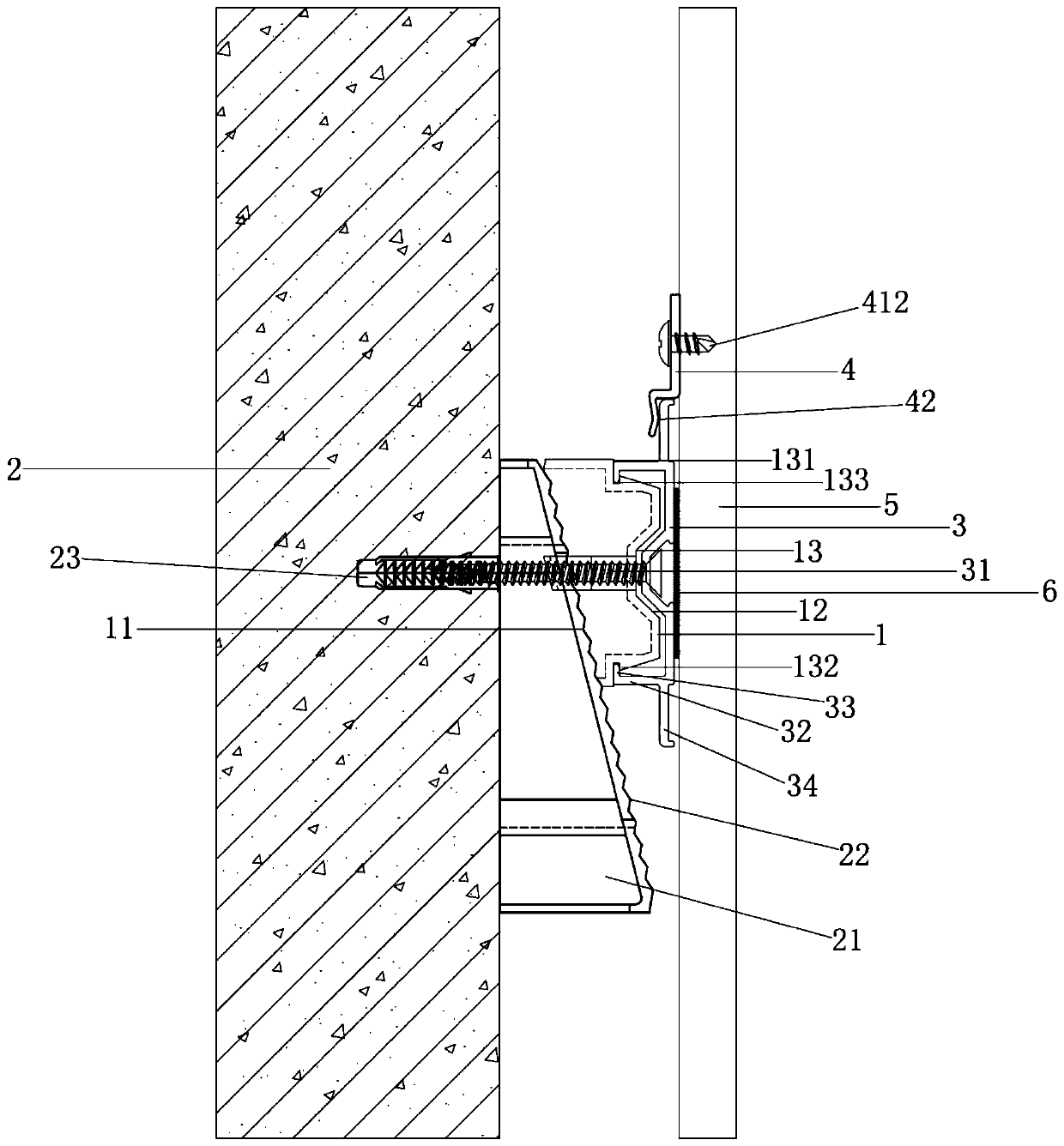
[0036] see Figure 1 to Figure 3 , the figure shows a portable wallboard dry-hanging installation structure provided by Embodiment 1 of the present invention, which mainly includes a first transverse keel 1 , a second transverse keel 3 , an adjustable dry-hanging member 4 and a wallboard 5 .

[0037] see Figure 1 to Figure 3 , the first transverse keel 1 has an opposite first connecting surface 11 and a second connecting surface 12, the first connecting surface 11 is connected to the wall 2, and the second connecting surface 12 has a The W-shaped bending surface 13, the opposite sides of the W-shaped bending surface 13 are respectively connected to the edge of the second connecting surface 12 through a step 131, and the edge of the W-shaped bending surface 13 forms an outwardly extending chamfer at the step 131 A locking groove 133 is formed between the surface 132 , the end of the chamfered surface 132 and the step 131 .

[0038] see Figure 1 to Figure 3 , the second tra...

Embodiment 2

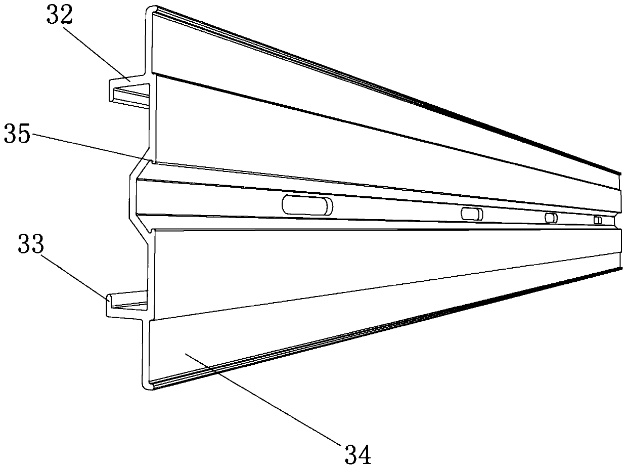
[0044] see Figure 1 to Figure 3 , the figure shows a portable wallboard dry-hanging installation structure provided by Embodiment 2 of the present invention. This embodiment further makes the following technical solutions as improvements on the basis of the above-mentioned embodiments: first The central part of the transverse keel 1 is a U-shaped bend extending toward the wall 2, and its opposite sides form a bell mouth structure. The central part of the second transverse keel 3 matches the shape of the central part of the first transverse keel 1, and the first There is a U-shaped gap between the central part of the transverse keel 1 and the central part of the second transverse keel 3, and the opposite sides of the central part of the second transverse keel 3 are respectively formed to extend into the central part of the second transverse keel 3. Convex edge 35. Through the setting of the above structure, the setting of the U-shaped gap can ensure that the screw will not be...

Embodiment 3

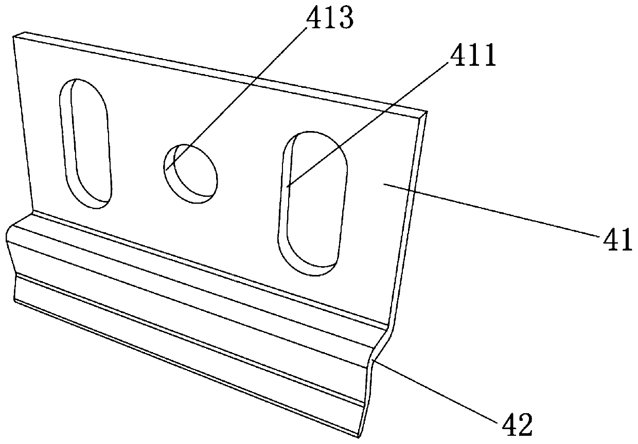
[0046] see Figure 1 to Figure 3, the figure shows a portable wallboard dry-hanging installation structure provided by Embodiment 3 of the present invention. On the basis of the above-mentioned embodiments, this embodiment further makes the following technical solutions as improvements: dry-hanging The main body 41 is provided with two parallel waist-shaped holes 411, and the screw 412 penetrates into the waist-shaped holes 411 to fix the wallboard 5 on the main body 41 of the dry hanging piece, and a screw hole is arranged between the two adjacent waist-shaped holes 411 413. Through the setting of the above-mentioned structure, the installation height of the dry hanger can be adjusted conveniently through the waist-shaped hole, and the position of the dry hanger can be locked through the screw hole after adjustment.


PUM


Abstract

The invention provides a convenient wall panel dry hanging installation structure. The convenient wall panel dry hanging installation structure includes a first transverse keel, a second transverse keel, an adjustable dry hanging piece and a wall panel, wherein the first transverse keel is connected to a wall, the first transverse keel is provided with a W-shaped bending surface, the two oppositesides of the W-shaped bending surface are correspondingly connected with the edges of second connecting surfaces through a step, the edges of the W-shaped bending surface form chamfered surfaces extending outwards at the step, and clamping grooves are formed between the end parts of the chamfered surfaces and the step; the second transverse keel is bent into a W shape, the center part of the second transverse keel is connected to the center part of the first transverse keel through screws in a screw joint mode, and two right angle bending hooks are correspondingly arranged on the two oppositesides of the second transverse keel and are clamped into the clamping grooves; the adjustable dry hanging piece includes a dry hanging piece body and an elastic plate, the side of the dry hanging piece body is in an L shape, and the elastic plate is fixedly connected to the bottom end of the dry hanging piece body; and the wall panel is fixedly connected to the dry hanging piece body. The invention further provides an installation method. According to the convenient wall panel dry hanging installation structure and method, the construction cost can be reduced, manual positioning is not required, the construction is more convenient, and the loosening phenomenon is reduced.

Description

technical field [0001] The invention relates to a wallboard dry-hanging installation structure, in particular to a convenient wallboard dry-hanging installation structure and an installation method. Background technique [0002] At present, in the prefabricated wall decoration construction, in order to meet the rapid construction and installation and reduce the construction requirements for workers, the dry-hanging wallboard system construction method is adopted. And existing dry-hanging wall panel system also has the following problems: [0003] 1) Positioning: Because the dry hanging parts are installed on the back of the wall panel and are not within the visible range, the workers cannot see the location of the dry hanging parts during construction. Therefore, there are difficulties in the positioning of the dry hanging parts. Unstable hanging can easily cause the wall panels to tilt Uneven; [0004] 2) Increased process and cost: When the base wall is uneven, the keel ...

Claims


Application Information

Patent Timeline
Patent Type & Authority Applications(China)
IPC IPC(8): E04F13/23E04F13/25
CPCE04F13/0803E04F13/083
Inventor 陆晓朋于利凯何志伟
Owner GOLD MANTIS FINE DECORATION TECH SUZHOU CO LTD
Why Eureka
Try Eureka