Steel pipe piece device for freezing soil around tail of shield tunneling machine and construction method of steel pipe piece device

A technology for the surrounding soil and shield machines, which is applied in the direction of measuring devices, earth drilling, shaft equipment, etc., and can solve problems such as poor uniformity in the circumferential direction of the frozen soil curtain, penetrating damaged segments, and hidden dangers of permanent leakage. , to improve cooling efficiency, reduce heat convection, and increase contact area

Pending Publication Date: 2020-12-11
CCCC SECOND HARBOR ENG
View PDF0 Cites 2 Cited by
  • Summary
  • Abstract
  • Description
  • Claims
  • Application Information

AI Technical Summary

Problems solved by technology

In the freezing scheme of replacing the tail brush, the conventional freezing method is difficult to realize, and it is necessary to design a special form and structure of the freezing tube within the low temperature adaptability range of the shield steel and segmental concrete
The conventional practice of drilling holes in the concrete segments at corresponding positions in the tunnel for freezing has penetrating damage to the segments, which can lead to defects such as permanent leakage hazards and poor circumferential uniformity of the frozen soil curtain
In addition, a small number of projects in China have used built-in freezing pipes in concrete segments. Due to the tightness of the freezing pipes, once leakage occurs, it cannot be compensated.

Method used


Image

  • Steel pipe piece device for freezing soil around tail of shield tunneling machine and construction method of steel pipe piece device
  • Steel pipe piece device for freezing soil around tail of shield tunneling machine and construction method of steel pipe piece device
  • Steel pipe piece device for freezing soil around tail of shield tunneling machine and construction method of steel pipe piece device

Examples


Embodiment Construction

[0032] The present invention will be further described in detail below in conjunction with the accompanying drawings, so that those skilled in the art can implement it with reference to the description.

[0033] It should be understood that terms such as "having", "comprising" and "including" as used herein do not entail the presence or addition of one or more other elements or combinations thereof.

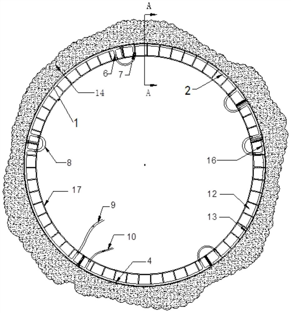
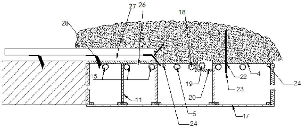
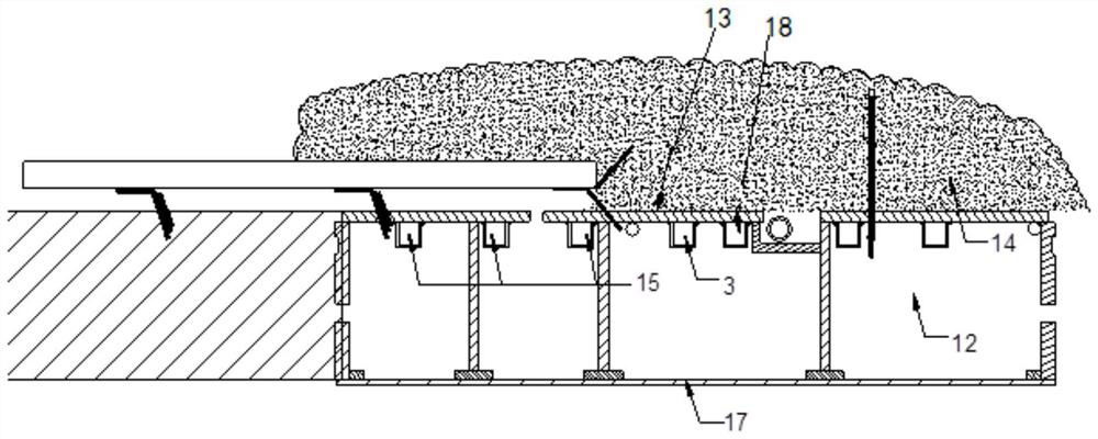
[0034] Such as Figure 1~4 As shown, the steel pipe sheet device for freezing the soil around the tail of the shield machine provided by the embodiment of the present invention includes: a plurality of arc-shaped steel pipe sheets 4, which are connected in sequence to form an annular steel pipe sheet 1; freezing pipeline 2, On the inner surface of each arc-shaped steel pipe sheet 4, multiple rows of freezing pipelines 2 are arranged along the arc, and the same row of freezing pipelines 2 on adjacent arc-shaped steel pipe sheets 4 are connected by a first pipe 8 to form multiple r...


PUM


Abstract

The invention discloses a steel pipe piece device for freezing soil around the tail of a shield tunneling machine. The steel pipe piece device comprises a plurality of arc-shaped steel pipe pieces, freezing pipelines and rib plates, wherein the arc-shaped steel pipe pieces are sequentially connected to form annular steel pipe pieces; a plurality of rows of freezing pipelines are arranged on the inner surface of each arc-shaped steel pipe piece along an arc line, the freezing pipelines on the same row of the adjacent arc-shaped steel pipe pieces are connected through first pipes to form a plurality of annular freezing pipelines, and secondary refrigerants in the annular freezing pipelines enable the temperature of the annular steel pipe pieces to be reduced, so that the soil around the annular steel pipe pieces is frozen; and the rib plates are arranged on the inner surfaces of the arc-shaped steel pipe pieces, rib plate cavities are formed, the rib plate cavities are filled with greasewith low freezing point, and an annular thin plate is arranged at the end of each rib plate and used for blocking the corresponding rib plate cavity so as to prevent the grease from falling off. Thedevice can efficiently freeze the soil around the tail of the shield tunneling machine, so that a circle of uniform freezing curtain is formed at the tail of the shield tunneling machine, and water and soil outside a shield tail gap are blocked. The invention further discloses a construction method for replacing a tail brush of the shield tunneling machine.

Description

technical field [0001] The invention relates to the replacement of a shield tunnel construction tail brush. More specifically, the present invention relates to a steel pipe sheet device for freezing soil around the tail of a shield machine and a construction method thereof. Background technique [0002] With the acceleration of urbanization, subway tunnel sections are getting longer and longer, and shield tunneling under complex geology is becoming more frequent. The excavation construction of long-distance and complex strata with shield tunneling has also become an inevitable trend. During the long-distance excavation of the shield machine, the shield tail sealing wire brush (hereinafter referred to as "shield tail brush"), which is one of the main sealing parts of the shield machine, is very easy to damage and difficult to repair. There is a certain gap between the outer wall of the shield segment and the inner side of the shield tail. The biggest difficulty in replaceme...

Claims


Application Information

Patent Timeline
Patent Type & Authority Applications(China)
IPC IPC(8): E21D9/00E21D11/38E21D9/06E21D11/18E21D11/22G01K13/00
CPCE21D9/001E21D9/06E21D11/18E21D11/22E21D11/38G01K13/00
Inventor 马超李聪唐天龙蔡超君刘坚松曾红波杨擎许超杨志勇刘东军熊栋栋刘杰贺创波高如超陈祥龙余俊钟涵张飞雷
Owner CCCC SECOND HARBOR ENG
Why Eureka
Try Eureka