Automobile switch detection working circuit structure

A switch detection and working circuit technology, applied in the direction of measuring electricity, measuring electrical variables, circuit breaker testing, etc., can solve the situation that is not suitable for interface circuit design, high negative pressure and positive pressure pulse signals, and the total cable length of vehicle equipment and other issues, to achieve the effect of flexible PCB design layout, stable network level, and short procurement cycle

Pending Publication Date: 2020-02-07
新阳荣乐(上海)汽车电子有限公司
View PDF0 Cites 0 Cited by
  • Summary
  • Abstract
  • Description
  • Claims
  • Application Information

AI Technical Summary

Problems solved by technology

[0004] 1. The NPN transistor needs a certain conduction voltage and driving current to turn on. The total cable of the vehicle equipment is long, and the voltage and current at the source end are relatively large. If it is a power level signal, the improper selection of the resistor will cause a large loss; Influenced by level changes, the size of the triode collector circuit ICQ is affected by changes in the environment and input level. According to the static DC operating point, after the change of IBQ=[Ui(input)-0.7V] / R, plus the environmental impact The magnification also changes accordingly, ICQ=magnification factor*IBQ, the loss is higher;
[0005] 2. The unrealized interface cable is affected by the coupling of the surrounding magnetic field, and the high-frequency noise affects the misoperation of this circuit and the impact on the system ground, especially in the test requirements for the control signal line in the EMC test project, injecting a higher load Pressure and positive pressure pulse signals;
[0006] 3. Generally, NPN triode has a certain withstand voltage range as a current-type drive switch, which is suitable for small signal and small voltage switch signal control in the system, and is not suitable for interface circuit design occasions.

Method used


Image

  • Automobile switch detection working circuit structure
  • Automobile switch detection working circuit structure
  • Automobile switch detection working circuit structure

Examples


Embodiment Construction

[0030] The following will clearly and completely describe the technical solutions in the embodiments of the present invention with reference to the accompanying drawings in the embodiments of the present invention. Obviously, the described embodiments are only some, not all, embodiments of the present invention. Based on the embodiments of the present invention, all other embodiments obtained by persons of ordinary skill in the art without making creative efforts belong to the protection scope of the present invention.

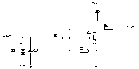
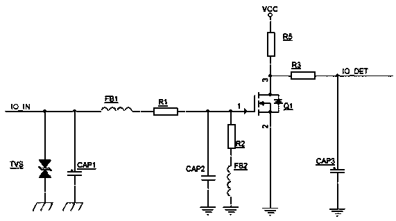
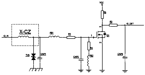
[0031] Such as figure 2 , 5 Shown, a kind of automobile switch detects working circuit structure, comprises interface signal input end, system detection end, power supply voltage end, electronic switch, antistatic TVS tube, capacitance to ground, resistance, at described interface signal input end and electronic switch A magnetic bead-based topology is added to the connection lines between them; the signal of the system detection terminal IO_DET defaults to ...


PUM


Abstract

The invention discloses an automobile switch detection working circuit structure. The automobile switch detection working circuit structure comprises an interface signal input end, a system detectionend, a power supply voltage end, an electronic switch, an anti-static TVS tube, a ground capacitor and a resistor. A topological structure based on magnetic beads is added in a connecting circuit between the interface signal input end and the electronic switch. The output of the interface signal input end is connected with a magnetic bead topological structure in series, the magnetic bead topological structure is connected with the ground capacitor in parallel, and the output signal of the magnetic bead topological structure enters a grid electrode of a field effect transistor after passing through a divider resistance structure to control the on or off of the electronic switch. The circuit structure can solve the problem that the cable is affected by the radiation of a surrounding magnetic field, hardly consumes the current of the input end, is suitable for level signals in a larger input range, and improves the integrity of interface signals and the stability of the system. Separatedcomponents are adopted in the circuit structure, the purchasing period is short, the PCB design layout is flexible, and the device cost is lower.

Description

technical field [0001] The invention relates to the technical field of automobile electronics, in particular to an automobile switch detection working circuit structure, which is used for detecting logic signals of automobile instruments and central control entertainment interfaces. Background technique [0002] The interface of automotive electronic equipment will have the detection of signal logic circuit. The levels of different level signals are not the same, and the working frequency is also different. Improper handling will not only affect the rectification of EMC testing, but also cause the system interface level to be unstable, affecting The system is running normally. Although the auxiliary interface cable can be used for shielding, the time and material costs will increase a lot, and it is not easy to implement. How to design a standardized, normalized, and unified circuit has become a technical problem. [0003] Existing programs such as figure 1 As shown, the c...

Claims


Application Information

Patent Timeline
Patent Type & Authority Applications(China)
IPC IPC(8): G01R31/327
CPCG01R31/3277
Inventor 孙凯瑾陶辉杨安涛
Owner 新阳荣乐(上海)汽车电子有限公司
Why Eureka
Try Eureka