Combined testing method and system for passive optical fiber equipment

A passive optical fiber and equipment technology, applied in the field of electronics, can solve the problems of high labor cost, too many products, too many test stations, etc., and achieve the effect of reducing operators, simplifying manufacturing costs, and reducing manufacturing costs.

Active Publication Date: 2022-05-20
ZHUHAI GOTECH INTELLIGENT TECH
View PDF16 Cites 0 Cited by
  • Summary
  • Abstract
  • Description
  • Claims
  • Application Information

AI Technical Summary

Problems solved by technology

[0004] The invention provides a combined testing method and system for passive optical fiber equipment, which is used to solve the production and testing process of Netcom products in the prior art. There are too many test stations, resulting in too many products in progress and failure to find out timely and effectively. The product is abnormal, and the product initialization time is too long, too many stations will also affect the operation efficiency, and the labor cost is also high

Method used


Image

  • Combined testing method and system for passive optical fiber equipment
  • Combined testing method and system for passive optical fiber equipment
  • Combined testing method and system for passive optical fiber equipment

Examples


Embodiment Construction

[0036] The technical solutions of the present invention will be described in detail below through the accompanying drawings and specific embodiments. It should be understood that the embodiments of the present invention and the specific technical features in the embodiments are only descriptions of the technical solutions of the present invention, rather than limitations. , the embodiments of the present invention and specific technical features in the embodiments may be combined with each other.

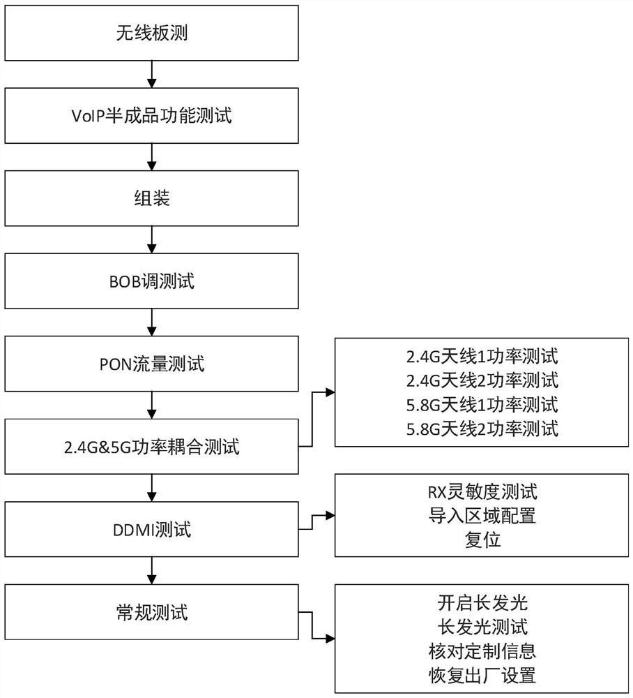
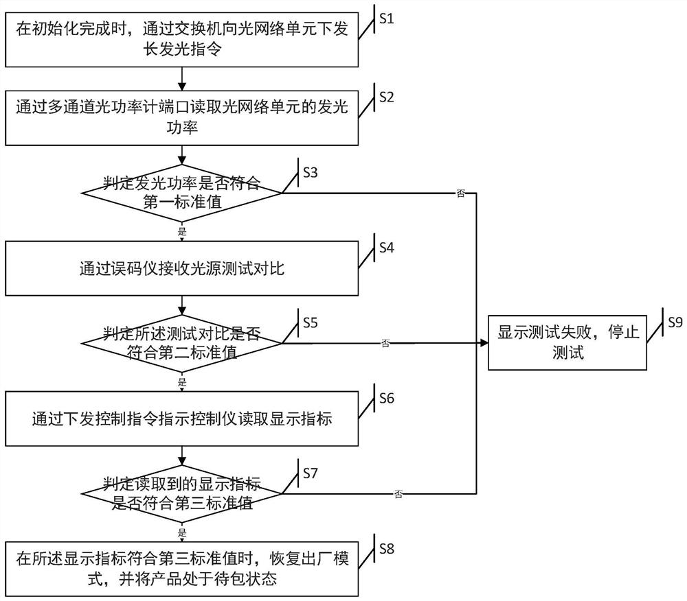
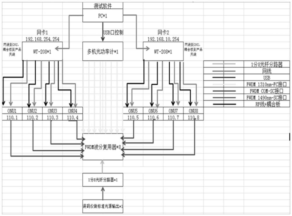
[0037] Such as figure 2 Shown is a flow chart of a combined testing method for passive optical fiber equipment in an embodiment of the present invention, the method is applied to such as image 3 In the system architecture shown, the system can include a PC, and the PC can run a software program corresponding to the method of the present invention. The system also includes a network card 1 and a network card 2, a multi-machine optical power meter, and a FWDM wavelength division mul...


PUM


Abstract

The invention discloses a combined test method and system for passive optical fiber equipment. Through the test process corresponding to the method provided by the invention, the product test platform can connect the coupling test station instrument to the optical power meter and the conventional test through the instrument instruction. The three test stations of BER tester + FWDM wavelength division multiplexer are integrated together, which reduces the number of operators, reduces manufacturing costs, reduces test process stations, and integrates test items. It has greatly promoted the simplification of the test process and the control of manufacturing costs.

Description

technical field [0001] The present application relates to the field of electronic technology, in particular to a combined testing method and system for passive optical fiber equipment. Background technique [0002] The predecessors of the fusion terminal are ONU and wireless router, which have been integrated into ONU+wireless router. Relevant test items and test process are more complex than before. The manpower used is also more than the previous single ONU and router, with the rise of labor costs in recent years. There are more and more optimizations of combined testing positions and projects. Such as figure 1 Shown is the current production and testing process of Netcom products. figure 1 It includes BOB test, PON test, 2.4G throughput test and 5G throughput test, DDMI test, and routine test. The wireless throughput test originally consisted of a 2.4G throughput test and a 5G throughput test. [0003] Judging from the current production and testing process of Netco...

Claims


Application Information

Patent Timeline
Patent Type & Authority Patents(China)
IPC IPC(8): H04Q11/00H04J14/02
CPCH04Q11/0067H04Q11/0005H04J14/0202H04Q2011/0083
Inventor 周杰周耀奕曾宪淦
Owner ZHUHAI GOTECH INTELLIGENT TECH
Why Eureka
Try Eureka