Arc crater adjustment device, welding system, arc crater adjustment method and computer program
A technology of adjustment device and adjustment unit, which is applied in the field of computer programs, can solve problems such as longer cycle time, adverse effects on weldability, and cycle time effects, and achieve the effect of shortening cycle time
- Summary
- Abstract
- Description
- Claims
- Application Information
AI Technical Summary
Problems solved by technology
Method used
Image

Examples
Embodiment approach 1
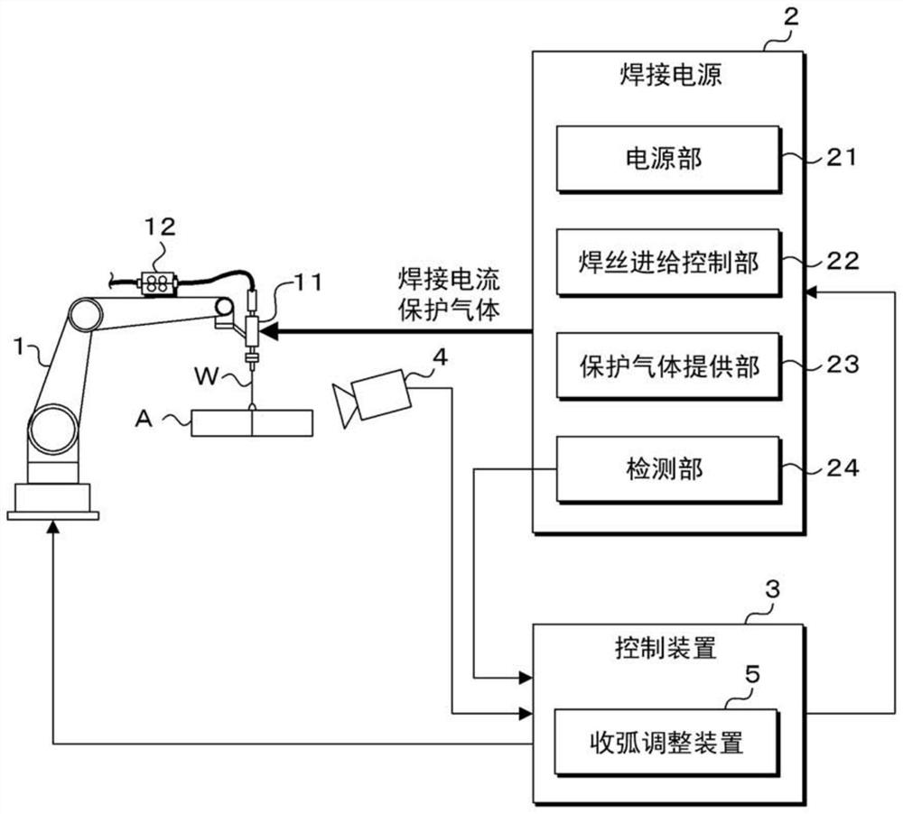
[0075] figure 1 It is a schematic diagram showing the arc welding system according to Embodiment 1. The arc welding system according to this embodiment is a consumable electrode type gas shielded arc welding machine, and includes a welding robot 1 , a welding power source 2 , a control device 3 , an imaging device 4 , and an arc crater adjustment device 5 . The arc crater adjustment device 5 is provided on the control device 3 . In addition, for the convenience of drawing and description, it is described that the components of the arc crater adjustment device 5 are included in the control device 3, but the control device 3 and the arc crater adjustment device 5 can also be a seamless structure, and it can also be seen that they are controlled by the control device. The hardware and software of the device 3 realize the function of the arc crater adjustment device 5 . In addition, the arc crater adjustment device 5 may be provided in the welding power source 2, or may be provi...
Embodiment approach 2
[0133] The arc crater adjustment device 205, the welding system, the arc crater adjustment method, and the computer program 50d according to the second embodiment are different from those of the first embodiment in that the process adjustment unit 55 and the shortest process storage unit 57 of the first embodiment are composed of a deep neural network. Therefore, the above-mentioned differences will be mainly explained below. Since other structures and effects are the same as those in the embodiment, corresponding parts are assigned the same reference numerals and detailed descriptions are omitted.
[0134] Figure 6 It is a functional block diagram showing the arc crater adjustment device 205 according to the second embodiment. The arc crater adjustment device 205 according to Embodiment 2 is the same as Embodiment 1, and includes a welding monitoring data acquisition unit 51a, an image data acquisition unit 51b, a first good / failure judging unit 52a, a second good / failure jud...
Embodiment approach 3
[0164] Figure 8It is a functional block diagram showing the arc crater adjustment device 305 according to the third embodiment. The arc crater adjustment device 305 , the welding system, the arc crater adjustment method, and the computer program 50d according to the third embodiment are different from those of the second embodiment in terms of data input to the process adjustment unit 355 , so the differences will be mainly described below. Since other structures and effects are the same as those in the embodiment, corresponding parts are assigned the same reference numerals and detailed descriptions are omitted.
[0165] The arc crater adjustment device 305 according to Embodiment 3 further includes a welding condition data acquisition unit 51c. The welding condition data acquisition part 51c acquires welding condition data. The welding condition data includes, for example, information such as the material of the base material A, the groove shape, the welding current setti...
PUM
 Abstract
Description
Claims
Application Information
 - R&D
- Intellectual Property
- Life Sciences
- Materials
- Tech Scout
- Unparalleled Data Quality
- Higher Quality Content
- 60% Fewer Hallucinations
Browse by: Latest US Patents, China's latest patents, Technical Efficacy Thesaurus, Application Domain, Technology Topic, Popular Technical Reports.
© 2025 PatSnap. All rights reserved.Legal|Privacy policy|Modern Slavery Act Transparency Statement|Sitemap|About US| Contact US: help@patsnap.com