Drill jig for plow colter speed-changing gear box

A gearbox and gear technology, which is applied in the field of coulter gear gearbox drilling machine fixtures, can solve the problems of slow clamping speed, low processing efficiency, complex fixture structure, etc., and achieve the goal of improving processing efficiency, high degree of automation, and simplifying fixture structure Effect

Active Publication Date: 2020-02-11
CHANGZHOU INST OF MECHATRONIC TECH
View PDF5 Cites 0 Cited by
  • Summary
  • Abstract
  • Description
  • Claims
  • Application Information

AI Technical Summary

Problems solved by technology

[0004] The technical problem to be solved by the present invention is: in order to solve the complex structure of the fixture for clamping the box of the coulter gear box in the drilling process of the box body installation surface of the coulter gear box in the prior art, The clamping speed is slow and the processing efficiency is low. The present invention provides a coulter gear gearbox drilling machine fixture to solve the above problems.

Method used


Image

  • Drill jig for plow colter speed-changing gear box
  • Drill jig for plow colter speed-changing gear box
  • Drill jig for plow colter speed-changing gear box

Examples


Embodiment Construction

[0034] Embodiments of the present invention are described in detail below, examples of which are shown in the drawings, wherein the same or similar reference numerals designate the same or similar elements or elements having the same or similar functions throughout. The embodiments described below by referring to the figures are exemplary only for explaining the present invention and should not be construed as limiting the present invention.

[0035] In describing the present invention, it should be understood that the terms "center", "upper", "lower", "top", "bottom", "inner", "outer", "axial" and the like indicate orientation or The positional relationship is based on the orientation or positional relationship shown in the drawings, which is only for the convenience of describing the present invention and simplifying the description, rather than indicating or implying that the referred device or element must have a specific orientation, be constructed and operated in a specif...


PUM


Abstract

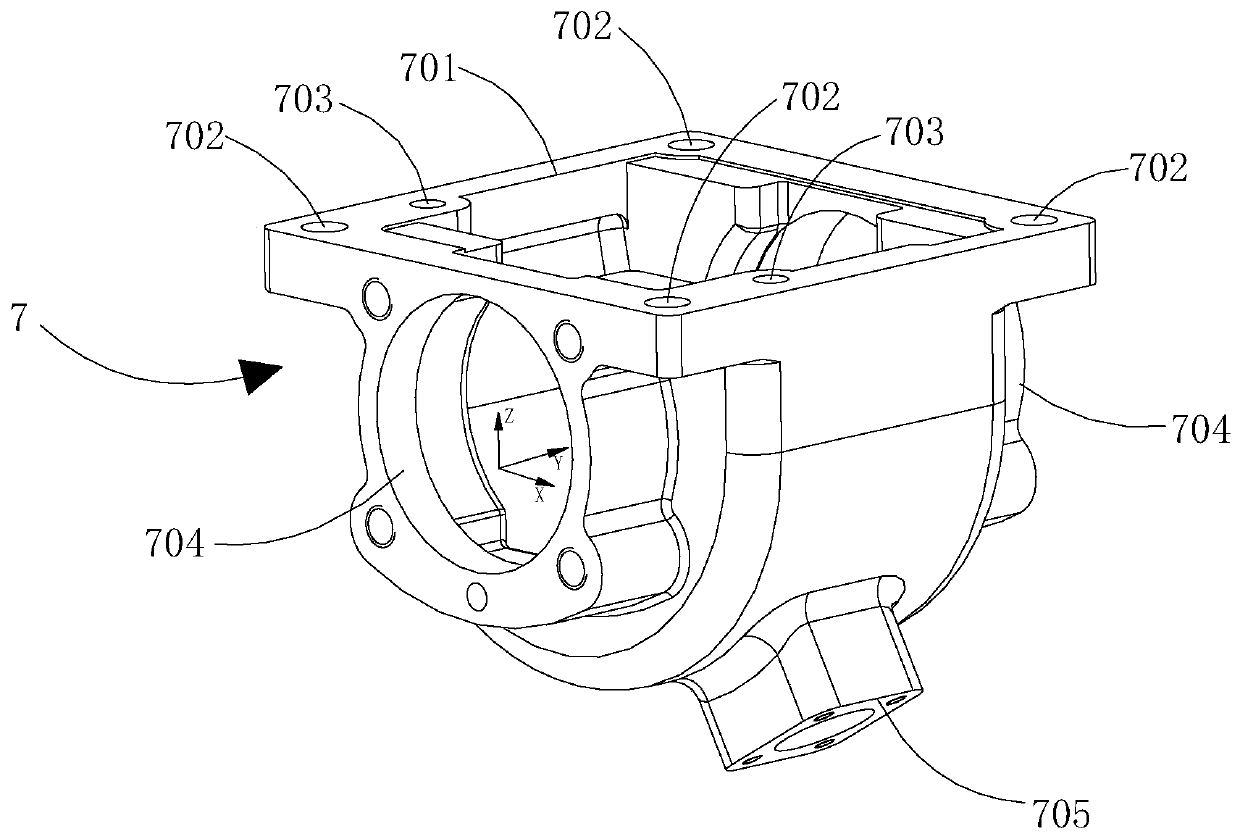
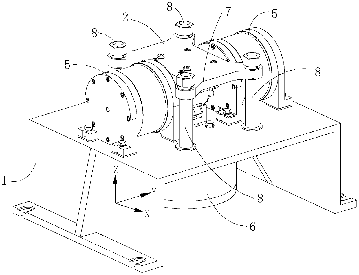
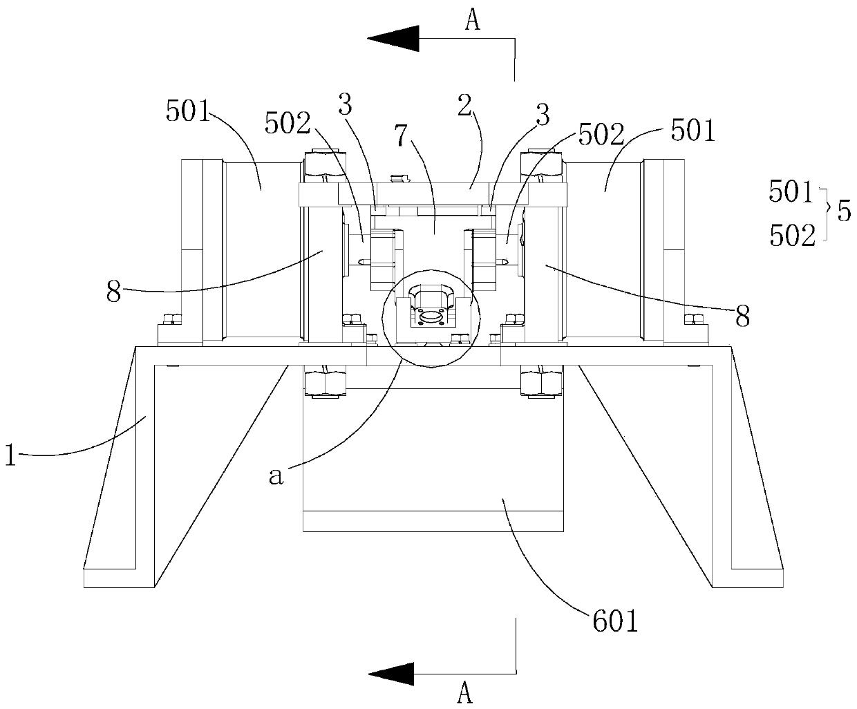
The invention discloses a drill jig for a plow colter speed-changing gear box. The drill jig comprises a base, a drill plate, an end face positioning assembly, a lateral positioning block, an axis endpositioning assembly and a press piece, wherein the drill plate is fixed to the upper side of the base through upright columns, and a workpiece is located between the drill plate and the base; the end face positioning assembly is connected to the bottom of the drill plate and used for limiting a to-be-defined end face to be parallel to the end face of the drill plate; the lateral positioning block is connected to the bottom of the drill plate and used for limiting the degree of freedom of the displacement, in the X direction, of the workpiece; the axis end positioning assembly is fixed to thetop of the base and used for positioning the center axis of the workpiece; the press piece is located on the top of the base and used for pressing the workpiece between the press piece and the drillplate. According to the unique appearance structure of the workpiece, the structure of the jig is simplified under the condition that the end face drilling processing requirements are met, therefore,the loading and clamping speed is greatly increased, and the processing efficiency is improved.

Description

technical field [0001] The invention relates to the technical field of mechanical processing, in particular to the technical field of clamping tools, in particular to a coulter gear gearbox drilling machine clamp. Background technique [0002] The box structure of the coulter gear box (hereinafter referred to as the workpiece) has a boss slope on the circumferential side. When the mounting surface on the workpiece circumference side is processed, the boss slope will affect the positioning of the workpiece, so use Ordinary plane clamps cannot achieve accurate positioning and clamping, and often need to use many auxiliary tools or use multiple angles superimposed, the clamping speed is greatly reduced, the structure of the clamping tool is complex, and the processing cost is high. Therefore, it is necessary to design a suitable for Clamping tool for the box structure of the coulter gear box. [0003] The present invention is a clamping tool designed for the drilling process o...

Claims


Application Information

Patent Timeline
Patent Type & Authority Applications(China)
IPC IPC(8): B23B47/28
CPCB23B47/28B23B2247/12
Inventor 冯纪良
Owner CHANGZHOU INST OF MECHATRONIC TECH
Why Eureka
Try Eureka