LED point light source wire welding machine and welding abutting mechanism thereof

A technology of welding ends and pressing parts, applied in the field of LED point light source assembly, can solve the problems of low reliability, easy warping of the wire core, virtual welding or de-soldering between the wire core and the PCB circuit board, etc., so as to improve the welding efficiency. , Avoid false welding and false welding, avoid the effect of multiple alignment operations

Pending Publication Date: 2020-02-11
SHENZHEN EX LIGHTING TECH HLDG
View PDF0 Cites 0 Cited by
  • Summary
  • Abstract
  • Description
  • Claims
  • Application Information

AI Technical Summary

Problems solved by technology

However, when the wire is positioned by pressing down, the wire core at the end of the wire is easy to lift, resulting in false welding or desoldering of the wire core and the PCB circuit board during final welding, and the reliability is not high; moreover, the existing wire generally has multiple wire core, and the welding head of the existing wire welding machine is in one-to-one correspondence with the wire core. The pads on the PCB are re-aligned, and the soldering efficiency is low

Method used


Image

  • LED point light source wire welding machine and welding abutting mechanism thereof
  • LED point light source wire welding machine and welding abutting mechanism thereof
  • LED point light source wire welding machine and welding abutting mechanism thereof

Examples


Embodiment Construction

[0019] The present application will be further described in detail below with reference to the accompanying drawings and specific embodiments. It should be understood that the following exemplary embodiments and descriptions are only used to explain the present invention, but not to limit the present invention, and, in the case of no conflict, the embodiments in the present application and the features in the embodiments can be combined with each other .

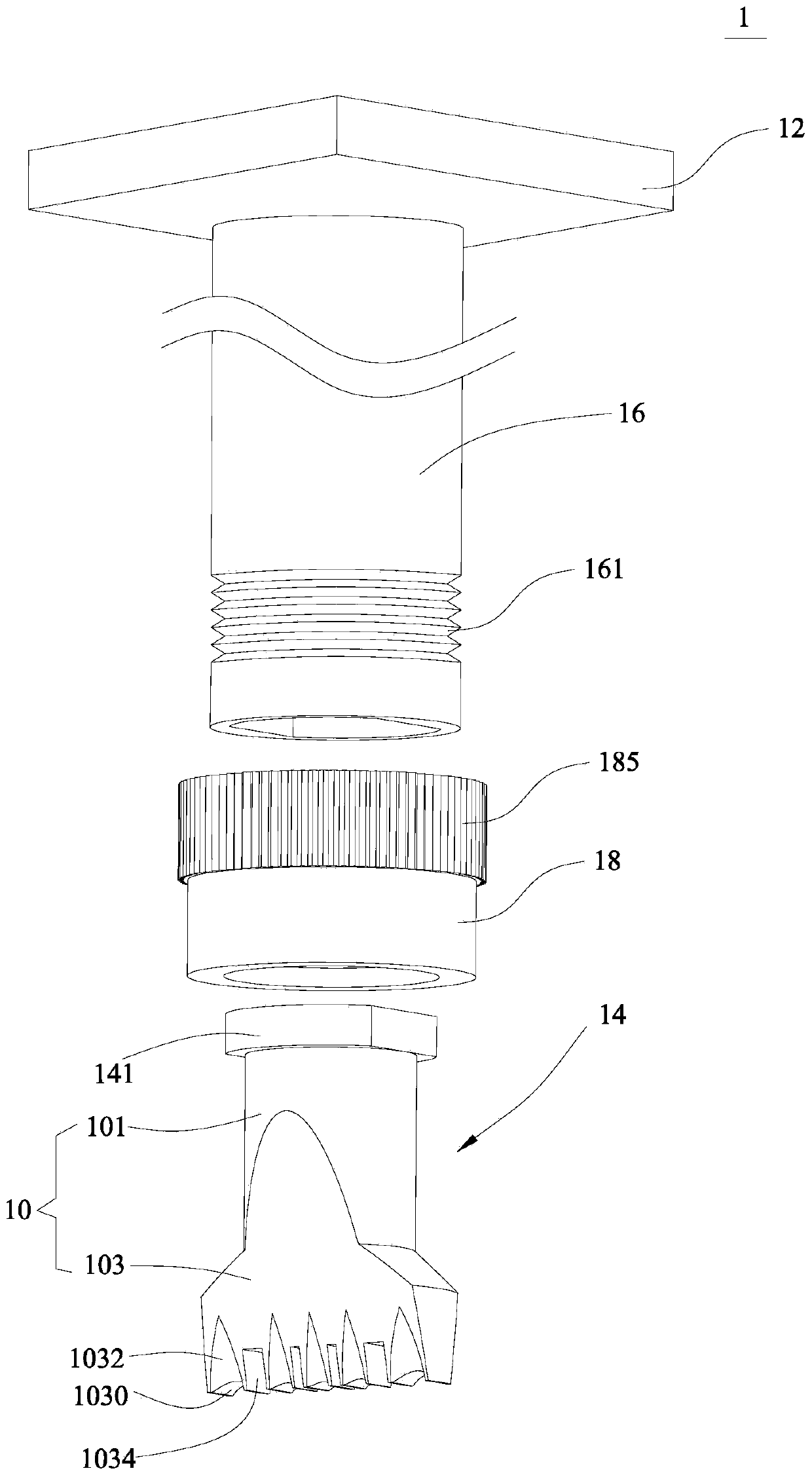
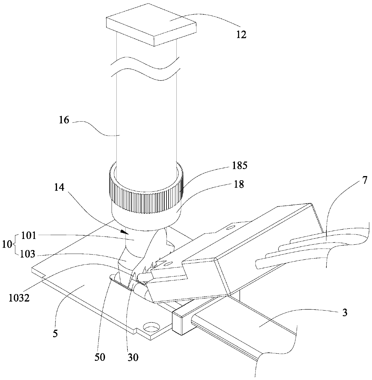
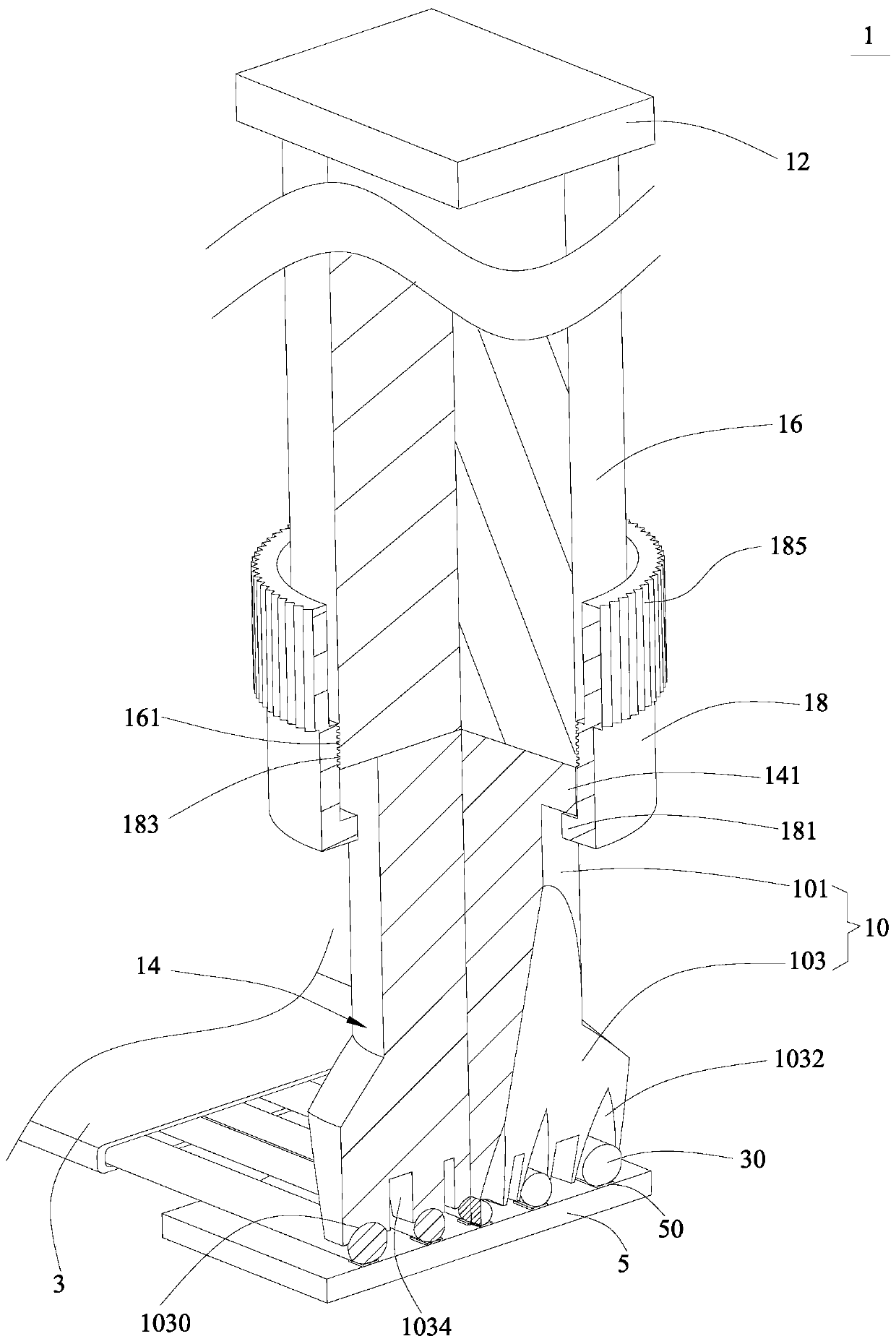
[0020] like Figure 1-Figure 2 As shown, an optional embodiment of the present invention provides a welding abutting mechanism 1, comprising a pressing member 10 for abutting the welding end 30 of the wire core of the wire 3 to be welded, and driving the pressing member 10 to move to The soldering end 30 is correspondingly pressed to the driving member 12 on the pad 50 of the PCB circuit board 5 which is correspondingly connected to the soldering end 30 , and the pressing member 10 includes the output of the driving member ...


PUM


Abstract

The embodiment of the invention provides an LED point light source wire welding machine and a welding abutting mechanism thereof. The welding abutting mechanism comprises an abutting part used for abutting against the welding ends of wire cores of a to-be-welded wire and a driving part used for driving the abutting part to move to correspondingly compress the welding ends to a welding disc of a PCB which is correspondingly connected with the welding ends in a welding manner; and the abutting part comprises a main body portion relatively fixed to the output end of the driving part and an abutting portion formed in the mode of extending from one end of the main body portion, and the end face of the end, far away from the main body portion, of the abutting portion is concaved to form a plurality of wire pressing grooves which are distributed at preset distances in parallel so as to correspondingly position and abut against the welding ends of the wire cores of the to-be-welded wire. According to the LED point light source wire welding machine and the welding abutting mechanism thereof, in the specific welding process, any one wire pressing groove of the abutting part only needs to bealigned with the corresponding welding disc of the PCB, repeated alignment is avoided, only the specific abutting part needs to be replaced for different specifications of wires, great convenience isachieved, the welding efficiency is high, and false welding and pseudo welding are avoided.

Description

technical field [0001] Embodiments of the present invention relate to the technical field of LED point light source assembly, and in particular, to an LED point light source wire bonding machine and a welding pressing mechanism thereof. Background technique [0002] The LED point light source usually needs to weld the wire and the PCB circuit board to form a wire assembly. The existing welding method is to put the PCB circuit board and the wire rod into a special welding positioning jig to press down and position the PCB circuit board and the wire rod, and then start the wire bonding machine to weld the PCB circuit board and the wire rod. However, when the wire rod is positioned under pressure, the wire core at the end of the wire rod is easily lifted, resulting in virtual welding or de-soldering between the wire core and the PCB circuit board during final welding, and the reliability is not high; moreover, the existing wire rods generally have many There is a wire core, an...

Claims


Application Information

Patent Timeline
Patent Type & Authority Applications(China)
IPC IPC(8): B23K3/08B23K3/00
CPCB23K3/00B23K3/08B23K3/087
Inventor 李剑郭庆水郭群涛马路
Owner SHENZHEN EX LIGHTING TECH HLDG
Why Eureka
Try Eureka