
Minimal quantity lubrication system applied to facing-type cutter

A micro-lubrication, face milling cutter technology, used in measuring/indicating equipment, metal processing machinery parts, maintenance and safety accessories, etc., can solve problems such as difficulty in uniform lubrication, increased tool wear, loss of nozzle flow, etc. Insufficient and excessive lubrication, improved lubrication quality, wide range of effects

Inactive Publication Date: 2020-02-11
SHANGHAI UNIV OF ENG SCI
View PDF7 Cites 4 Cited by
  • Summary
  • Abstract
  • Description
  • Claims
  • Application Information

AI Technical Summary

Problems solved by technology

Most of the traditional micro-lubrication devices lubricate one surface of the tool, it is difficult to achieve uniform lubrication, and it will also increase the wear of the tool, which cannot meet the needs of finishing
The traditional micro-quantity lubrication device cannot adjust the flow rate of the micro-quantity lubrication nozzle according to the working temperature of the tool. It may damage the tool due to overheating of the tool or lose the advantage of micro-quantity lubrication due to excessive nozzle flow, which cannot meet actual needs.

Method used


Image

  • Minimal quantity lubrication system applied to facing-type cutter
  • Minimal quantity lubrication system applied to facing-type cutter
  • Minimal quantity lubrication system applied to facing-type cutter

Examples


Embodiment Construction

[0028] The technical solution of this patent application will be described in further detail below in conjunction with the accompanying drawings and specific embodiments.

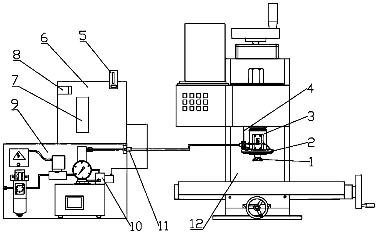
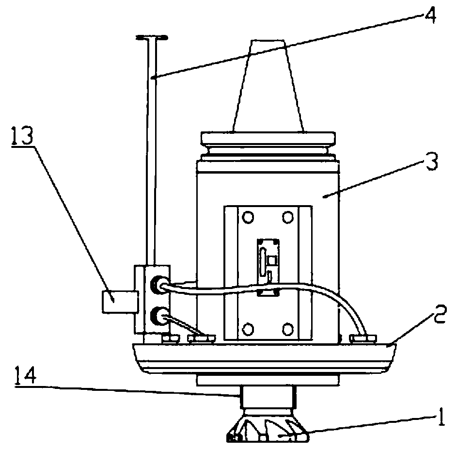
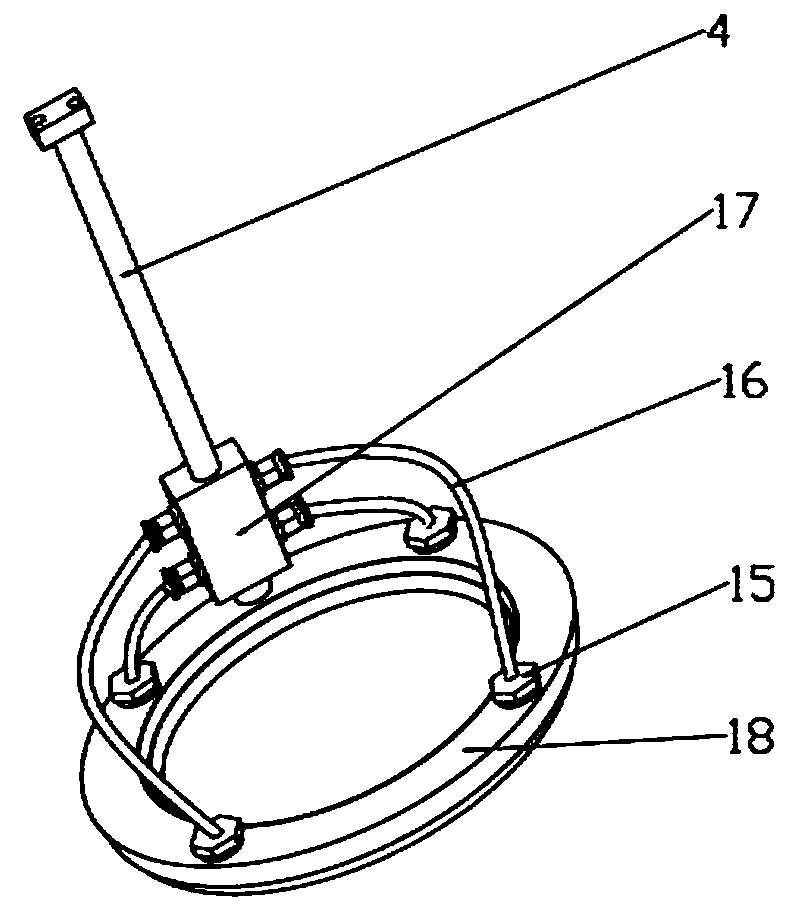
[0029] Such as figure 1 A minimal quantity lubrication system applied to a shell face milling cutter is shown, which mainly includes: an annular minimum quantity lubrication nozzle 2 fixed on a milling machine 12, a wireless temperature measuring mechanism 3 arranged on a cutter bar of a shell face milling cutter 1 and A single-chip microcomputer control system 6 that receives wireless temperature measurement data from the wireless temperature measurement mechanism 3 and controls the lubrication flow rate of the annular micro-lubrication nozzle. Preferably, an electromagnetic valve 10 is set on the minimum quantity lubrication oil supply circuit and controlled by a single-chip microcomputer control system 6 . The single-chip microcomputer control system 6 includes a single-chip microcomputer 7 and a wirele...


PUM


Abstract

The invention relates to a minimal quantity lubrication system applied to a facing-type cutter. The minimal quantity lubrication system involves a minimal quantity lubrication system, a wireless temperature measuring system and a control system, wherein the minimal quantity lubrication system comprises an annular minimal quantity lubrication nozzle, and the annular minimal quantity lubrication nozzle is arranged at the upper part of the facing-type cutter in a sleeve mode, the wireless temperature measuring system is arranged on a cutter rod of the facing-type cutter and is used for measuringthe temperature of the facing-type cutter and sending the temperature to the control system, and the control system is electrically connected with the wireless temperature measuring system and the minimal quantity lubrication system to control the lubricating flow of the annular minimal quantity lubrication nozzle according to the temperature of the facing-type cutter. According to the minimal quantity lubrication system, through cooperation of the minimal quantity lubrication system and the wireless temperature measuring system, the temperature change of a milling cutter is monitored in realtime in a milling process, the oil feeding flow of the annular minimal quantity lubrication nozzle is controlled in real time according to the temperature change range, and sufficient lubrication of the facing-type cutter is guaranteed.

Description

technical field [0001] The invention relates to the technical field of micro-lubrication, in particular to a micro-lubrication device applied to a shell face milling cutter. Background technique [0002] Minimal quantity lubrication refers to the lubrication condition in which the amount of lubricant is very small. It is also called minimum quantity lubrication in cutting. It is a lubrication method applied to metal processing. It can effectively reduce the friction between the tool and the workpiece, between the tool and the chip, prevent sticking, prolong the life of the tool, and improve the quality of the processed surface. Minimal Quantity Lubrication (MQL) technology reduces the amount of cutting fluid to a small amount, significantly reducing the cost of cutting fluid, and reduces the harm of cutting fluid to the environment and human body by using synthetic esters with high natural degradability as lubricants; Compared with dry cutting, MQL introduces cooling and lu...

Claims


Application Information

Patent Timeline
IPC IPC(8): B23Q11/10B23Q17/00
CPCB23Q11/10B23Q17/00Y02P70/10
Inventor 代文青王大中毛蔚蒋煜陈国庆付强吴淑晶
Owner SHANGHAI UNIV OF ENG SCI
Learn More