Waveguide display device adapted to VR equipment

A display device and waveguide technology, applied in the directions of light guides, optics, instruments, etc., can solve the problems of large viewing angle of the whole machine, limiting the viewing angle of the display system, and lens thickness, etc., and achieve the effect of improving portability.

Inactive Publication Date: 2020-02-11
平行现实(杭州)科技有限公司
View PDF9 Cites 0 Cited by
  • Summary
  • Abstract
  • Description
  • Claims
  • Application Information

AI Technical Summary

Problems solved by technology

The waveguide display combined with LCOS, DLP, MEMS and other micro-optical machines for AR display devices has the obvious advantages of thinness and portability, but its transparent properties are not suitable for VR immersive display
Moreover, the virtual image needs to use the technical characteristics of the total reflection principle to transmit in the waveguide layer, so that the light transmission in the waveguide layer must satisfy the condition that the incident angle is greater than the total reflection angle of the waveguide layer material. This feature greatly limits the viewing angle of the display system. field angle
On the other hand, most of the VR display devices on the market use a display combined with a traditional visual imaging system. The field of view is large, but the whole machine, especially the optical display system, is too bulky.
And because in the design process, in order to ensure high magnification and large field of view, it is necessary to increase the radius of curvature of the lens in the imaging system or increase the distance between the lens group and the display screen, and the improvement results of these two solutions are to play a role in magnification. The lens is very thick or the distance between the lens and the screen is too large. As a result, the volume and quality of the entire optical imaging system are too large, which affects the aesthetics, portability and wearing comfort of the VR device.

Method used


Image

  • Waveguide display device adapted to VR equipment
  • Waveguide display device adapted to VR equipment

Examples


Embodiment Construction

[0020] The present invention will be described in detail below with reference to the accompanying drawings and preferred embodiments, and the purpose and effect of the present invention will become clearer. It should be understood that the specific embodiments described here are only used to explain the present invention and are not intended to limit the present invention.

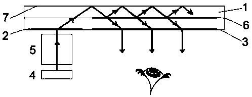
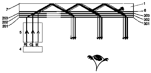
[0021] like figure 1 As shown, the waveguide display device adapted to VR equipment of the present invention includes an optical-mechanical module 4, an imaging module 5, and a waveguide module. The reflective film 7 and the reflective film 6 coated with gradient reflectivity disposed on the side of the waveguide layer 1 close to the human eye, the reflectivity gradually decreases from the coupling side to the side away from the coupling;

[0022] In order to realize light deflection, the waveguide display device may also include a coupling-in structure 2 and an out-coupling structure 3; the coupling-in st...


PUM


Abstract

The invention discloses a waveguide display device adapted to VR equipment. The device comprises an optical machine module, an imaging module and a waveguide module; the waveguide module comprises a waveguide layer, a total reflection film arranged in the side, away from the human eyes, of the waveguide layer and a reflection film arranged in the side, close to the human eyes, of the waveguide layer and plated with gradient reflectivity, and the reflectivity is gradually reduced from the coupling-in side to the side away from the coupling-in side; the optical-machine module generates incidentlight, the incident light is imaged by the imaging module, is input to the waveguide layer, reaches a total reflection film, and is reflected to the reflection film with gradually changed reflectivitysuccessively, most of light is reflected and further wave-guided forwardly, small part of light is transmitted out of the waveguide layer and received by the human eyes, the wave-guided forwardly part of light is still wave-guided partly and transmitted partly when making contact with a subsequent reflection film, and thus, a transmission and pupil expansion process is achieved. Thus, The VR equipment and the same type of display device are more portable, and the problem that a waveguide display technology is limited by the total reflection angle of the wave guide material is overcome.

Description

technical field [0001] The invention relates to the field of virtual reality (VR) equipment, in particular to a waveguide display device adapted to VR equipment. Background technique [0002] Existing waveguide technology has been gradually applied in AR (Augmented Reality) devices, mainly including waveguide layers based on the principle of total reflection, micro-optical-mechanical modules, imaging modules and grating structures for magnification and pupil expansion. The role of light coupling in and out of the chip. [0003] Among them, the waveguide layer and the grating layer (generally etched on the surface of the waveguide layer in the form of relief) are transparent, ensuring that realistic images can be transmitted to the human eye through them. At the same time, the virtual image is sent from the optical-mechanical module, and after passing through the imaging system, it is coupled into the waveguide layer by grating diffraction, transmitted in the waveguide layer...

Claims


Application Information

Patent Timeline
Patent Type & Authority Applications(China)
IPC IPC(8): G02B27/01G02B6/00
CPCG02B6/0055G02B27/0101G02B2027/0123
Inventor 鲍鹏飞
Owner 平行现实(杭州)科技有限公司
Why Eureka
Try Eureka