Numerical prediction method for size of bubbles in gas-liquid multiphase pump

A gas-liquid mixed pump and numerical prediction technology, which is applied in CAD numerical modeling, design optimization/simulation, etc., can solve the problem of affecting the accuracy of numerical prediction, unable to obtain the bubble size change law through numerical calculation, and unable to obtain the gas-liquid two-phase flow field and other issues to achieve the effect of improving transportation capacity and improving reliability

Inactive Publication Date: 2020-02-11
TSINGHUA UNIV
View PDF4 Cites 8 Cited by
  • Summary
  • Abstract
  • Description
  • Claims
  • Application Information

AI Technical Summary

Problems solved by technology

[0005] Due to the rotation of the impeller, static and dynamic interference, and the interaction between gas and liquid, the bubbles will inevitably aggregate and collapse in the mixed pump, and the size of the bubbles will inevitably change. The collapse and aggregation of bubbles are not considered in the simulation calculations, and the diameter of the bubbles is usually given a fixed value, which makes it impossible to obtain the change law of the bubble size in the mixing pump through numerical calculations
Obviously, the constant bubble size will in turn directly affect the most important resistance in the force between gas and liquid, which in turn affects the accuracy of numerical prediction, and it is impossible to obtain an accurate gas-liquid two-phase flow field
[0006] Therefore, it is hoped that there is a numerical prediction method for the bubble size in the gas-liquid mixed pump, which can solve the numerical simulation calculation problem of the gas-liquid two-phase flow in the mixed pump in the prior art.

Method used


Image

  • Numerical prediction method for size of bubbles in gas-liquid multiphase pump
  • Numerical prediction method for size of bubbles in gas-liquid multiphase pump
  • Numerical prediction method for size of bubbles in gas-liquid multiphase pump

Examples


Embodiment Construction

[0048] In order to make the objectives, technical solutions and advantages of the present invention clearer, the technical solutions in the embodiments of the present invention will be described in more detail below in conjunction with the drawings in the embodiments of the present invention. In the drawings, the same or similar reference numerals denote the same or similar elements or elements having the same or similar functions throughout. The described embodiments are some, but not all, embodiments of the invention. The embodiments described below by referring to the figures are exemplary and are intended to explain the present invention and should not be construed as limiting the present invention. Based on the embodiments of the present invention, all other embodiments obtained by persons of ordinary skill in the art without creative efforts fall within the protection scope of the present invention.

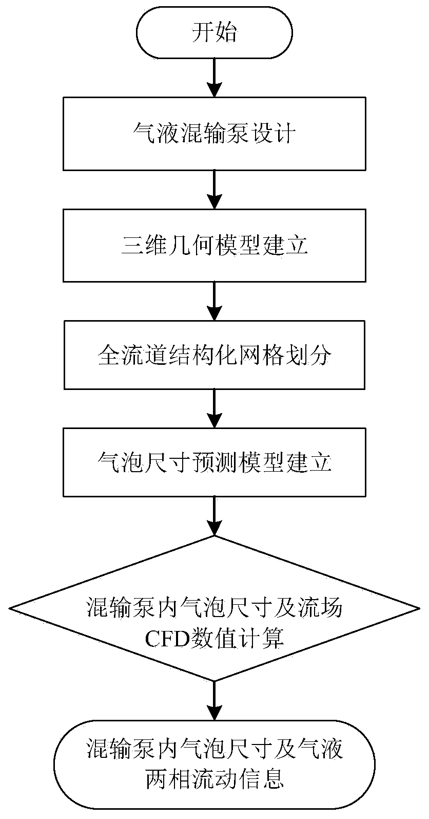
[0049] Such as figure 1 As shown, the numerical prediction method of t...


PUM


Abstract

The invention discloses a numerical prediction method for the size of bubbles in a gas-liquid multiphase pump, and the method comprises the following steps: 1, obtaining the final shapes of an impeller and a guide vane through the three-dimensional inverse problem design of the gas-liquid multiphase pump; 2, establishing a three-dimensional geometric model of the gas-liquid multiphase pump according to the step 1; 3, according to the geometric model in the step 2, carrying out full-flow-channel hexahedron structure grid division, and improving the grid quality by adopting different types of topological structures; 4, establishing a bubble size prediction model which comprises a basic control equation, a turbulence model and a bubble equation; 5, based on the bubble size prediction model inthe step 4, setting boundary conditions and solving parameters by adopting simulation calculation of computational fluid dynamics CFD, and carrying out numerical prediction on the bubble size and thegas-liquid two-phase flow field in the multiphase pump; and 6, carrying out post-processing analysis on the numerical calculation prediction in the step 5 to obtain a bubble size change rule in the impeller and the guide vane of the multiphase pump and gas-liquid two-phase flow field information.

Description

technical field [0001] The invention relates to the technical field of fluid mechanical multiphase flow numerical simulation, in particular to a numerical prediction method for the bubble size in a gas-liquid mixed transport pump. Background technique [0002] Gas-liquid mixed transport pumps are widely used in multi-phase mixed transport processes in petrochemical, food, nuclear industry and other fields. Compared with the traditional way of transporting gas and liquid separately, since there is no complicated separation equipment for multiphase mixed transportation, and the transportation medium shares a pipeline, the transportation efficiency is significantly improved and huge economic benefits are brought. For example, for the development of offshore oilfield resources, multi-phase mixed transportation means that the offshore platform can be replaced by a subsea booster pump station, and the capital construction investment cost can be reduced by about 40%. [0003] Two-...

Claims


Application Information

Patent Timeline
Patent Type & Authority Applications(China)
IPC IPC(8): G06F30/20G06F111/10
Inventor 祝宝山张文武
Owner TSINGHUA UNIV
Why Eureka
Try Eureka