Manufacturing method of electrode for solid state battery

A solid battery and manufacturing method technology, applied in the direction of electrode manufacturing, battery electrode, electrolyte battery manufacturing, etc., can solve the problems of battery temperature rise, battery adverse effects, etc., and achieve the effect of reducing electronic resistance

Active Publication Date: 2022-08-05
TOYOTA JIDOSHA KK
View PDF15 Cites 0 Cited by
  • Summary
  • Abstract
  • Description
  • Claims
  • Application Information

AI Technical Summary

Problems solved by technology

[0002] When a battery used as a power supply for vehicles, personal computers, portable terminals, etc. is misused due to internal short circuit, overcharge, etc., the temperature of the battery as a whole rises, which may adversely affect the battery itself and the equipment using the battery.

Method used


Image

  • Manufacturing method of electrode for solid state battery
  • Manufacturing method of electrode for solid state battery
  • Manufacturing method of electrode for solid state battery

Examples


no. 1 approach

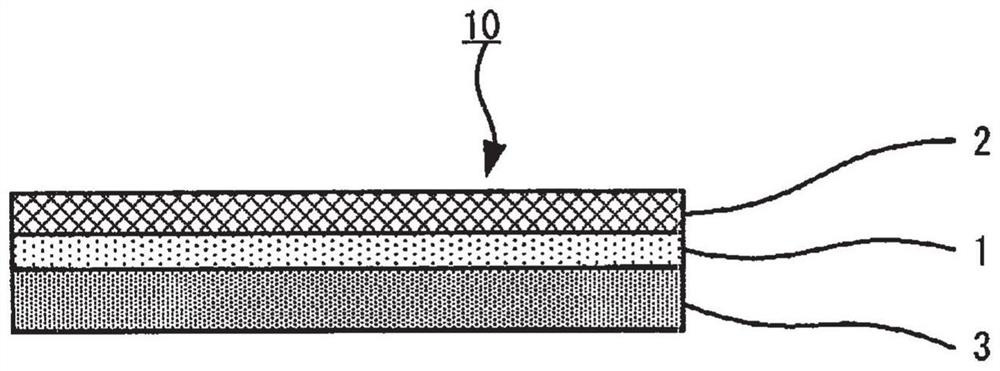
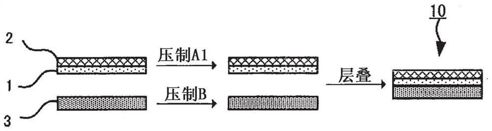
[0080] like figure 2 As shown, the first embodiment of the manufacturing method of the present disclosure is provided with at least two pressing steps: pressing step A1 of pressing the current collector with the PTC resistor layer formed thereon; and pressing the electrode active material having at least the electrode active material layer Pressing process B in which the component is pressed.

[0081] 2-1. The process of forming the PTC resistor body layer

[0082] In the step of forming the PTC resistor body layer of the first embodiment, the PTC resistor body layer is formed by coating the slurry containing the conductive material and the polymer on at least any surface of the current collector, followed by drying.

[0083] (1) Slurry

[0084] The paste contains a conductive material and a polymer.

[0085] The method for forming the PTC resistor body layer after applying the slurry on the current collector is not particularly limited, but generally, the conductive mater...

no. 2 approach

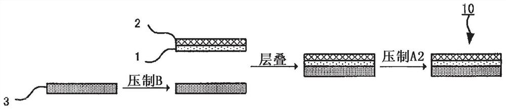
[0127] like image 3 As shown, the second embodiment of the manufacturing method of the present disclosure is provided with at least two pressing steps: pressing step B of pressing the electrode active material member having at least the electrode active material layer 3 in such a manner that the maximum pressure is b; and The electrode precursor having at least the current collector 2 , the electrode active material layer 3 and the PTC resistor layer 1 is subjected to a pressing step A2 of pressing so that the maximum pressure is a2 .

[0128] The first embodiment and the second embodiment are common in the following aspects: the aspect of having at least two pressing steps; the aspect of having the pressing step B of pressing at least the electrode active material member having the electrode active material layer; The aspect in which the maximum pressure b1 applied to the electrode active material layer is greater than the maximum pressure (a1 and a2) applied to the PTC resi...

Embodiment 1

[0153] (1-1) Step of Forming PTC Resistor Layer

[0154] Furnace black with an average primary particle size of 66 nm (manufactured by Tokai Carbon Co., Ltd.) as a conductive material, alumina as an insulating inorganic substance (particle size D90: 6 μm), and PVDF as a polymer (Kureha Co., Ltd.) were prepared Manufacture of KF Polymer L#9130). These were mixed with N-methylpyrrolidone as a solvent so as to have a volume ratio of furnace black:PVDF:alumina=10:30:60 to prepare a slurry. Then, the slurry was applied on an aluminum foil having a thickness of 15 μm, and dried in a stationary drying furnace under the conditions of 100° C. and 1 hour to form a PTC resistor layer.

[0155] (1-2) Pressing process A1

[0156] The current collector on which the PTC resistor layer was formed was rolled under the conditions of a pressing pressure a1 of 5.6 kN / cm (199 MPa in conversion) and room temperature to obtain a PTC resistor layer-current collector laminate.

[0157] (1-3) Pressing...


PUM

PropertyMeasurementUnit
thicknessaaaaaaaaaa

Abstract

The present invention relates to a method for producing an electrode for a solid state battery. The manufacturing method includes: coating a slurry containing a conductive material and a polymer on at least one surface of the current collector, followed by drying to form a PTC resistor layer; Pressing process A1 in which the current collector is pressed with a maximum pressure of a1; pressing process B in which the electrode active material member having at least the electrode active material layer but not the PTC resistor layer is pressed with a maximum pressure of b and the current collector formed with the PTC resistor body layer and the electrode active material member are stacked so that the PTC resistor body layer is in contact with the electrode active material layer, thereby obtaining a solid-state battery electrode process, in Each maximum pressure applied in the pressing process B and the pressing process A1 satisfies the following relationship: b>a1.

Description

technical field [0001] The present disclosure relates to methods of manufacturing electrodes for solid state batteries. Background technique [0002] When a battery used as a power source for a vehicle, a personal computer, or a portable terminal is misused, such as an internal short circuit or overcharge, the temperature of the entire battery increases, which may adversely affect the battery itself and devices using the battery. [0003] As a countermeasure against such misuse, an attempt has been made to use an electrode having a positive temperature coefficient (Positive Temperature Coefficient; PTC) resistor layer having electron conductivity at normal temperature , and the electronic resistance (electronic resistance) value increases sharply when the temperature increases due to misuse. [0004] Patent Document 1 discloses an all-solid-state battery comprising: a positive electrode layer having a positive electrode active material layer and a positive electrode current...

Claims


Application Information

Patent Timeline
Patent Type & Authority Patents(China)
IPC IPC(8): H01M50/581H01M4/04H01M10/42
CPCH01M4/0404H01M4/0435H01M10/4235H01M2200/106H01M50/581H01M4/13H01M4/139H01M4/667H01M4/668H01M4/043H01M4/366H01M10/058H01M10/0562H01M10/0525
Inventor 尾濑徳洋铃木知哉长谷川元八十和夫西村英晃松下祐贵
Owner TOYOTA JIDOSHA KK
Why Eureka
Try Eureka