Heat transfer device and heating system

A heat exchange device and heating system technology, which is applied in the direction of fuel cell heat exchange, reactant parameter control, fuel cell additives, etc., can solve the problem of low utilization rate of waste heat from fuel cell tail gas, and improve the comprehensive utilization efficiency of energy. Easy to disassemble and improve the effect of turbulence intensity

Active Publication Date: 2020-02-11
安徽伯华氢能源科技有限公司
View PDF7 Cites 6 Cited by
  • Summary
  • Abstract
  • Description
  • Claims
  • Application Information

AI Technical Summary

Problems solved by technology

[0008] The technical problem to be solved by the present invention is: how to solve the problem of low waste heat utilization rate in the existing fuel cell exhaust

Method used


Image

  • Heat transfer device and heating system
  • Heat transfer device and heating system
  • Heat transfer device and heating system

Examples


Embodiment 1

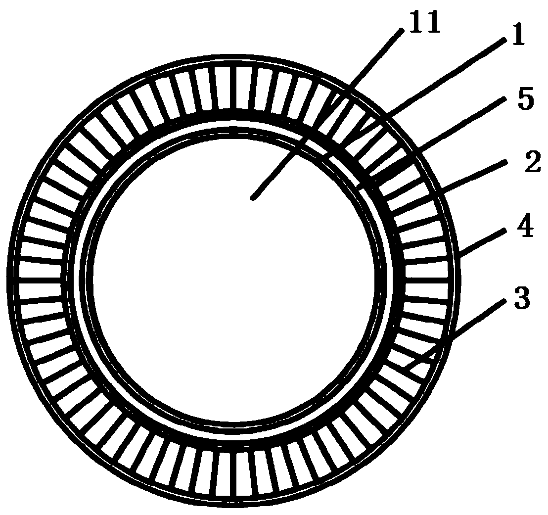
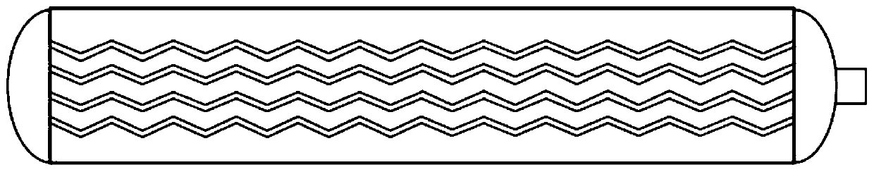
[0035] Such as figure 1 , 2 As shown, a heat exchange device is arranged outside the hydrogen storage tank 1, and inside the hydrogen storage tank 1 is a metal hydride reaction bed 11 capable of generating hydrogen, including an inner sleeve 2 arranged at a distance from the hydrogen storage tank, and the inner sleeve 2 The outer wall is provided with a plurality of fins 3 , and an outer sleeve 4 is arranged outside the fins 3 .

[0036] In this embodiment, the inner sleeve 2 and the outer sleeve 4 are cylindrical structures. In order to facilitate installation and disassembly, they can be set to a detachable structure. , card connection, etc., and then assemble the split type into an integral structure.

[0037] In this embodiment, the fins 3 are fins with a corrugated structure, and are arranged along the outer wall of the inner sleeve 2 along the circumferential direction. The outer surface of the hydrogen storage tank 1 is usually a smooth surface, and the outer surface ...

Embodiment 2

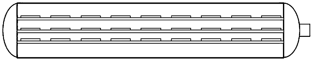
[0041] Such as image 3 As shown, the difference between this embodiment and the first embodiment lies in that the structure of the fins 3 is different.

[0042] The fins 3 in this embodiment are fins with a slit structure.

Embodiment 3

[0044] Such as Figure 4 As shown, the difference between this embodiment and the first embodiment lies in that the structure of the fins 3 is different.

[0045] The fins 3 in this embodiment are fins with a louver structure.


PUM


Abstract

The invention discloses a heat transfer device, which is arranged outside a hydrogen storage tank and includes an inner sleeve spaced apart from the hydrogen storage tank. The outer wall of the innersleeve is provided with a plurality of fins. An outer sleeve is disposed outside the fins. The invention also discloses a heating system using the heat transfer device. The heating system includes a fuel cell, the hydrogen storage tank, a hydrogen supply pipe, an air inlet pipe, a fuel cell exhaust gas pipe or a cooling system, and the heat transfer device. The heat transfer device is disposed atthe hydrogen storage tank to transfer heat and increase turbulence intensity, thereby improving the heat transfer efficiency. The heating system, on the one hand, helps to reduce system energy consumption and improve comprehensive energy utilization efficiency, and on the other hand, achieves effective control of the hydrogen desorption working temperature of the hydrogen storage tank, and realizes the utilization of the maximum effective hydrogen storage capacity of a hydrogen storage system.

Description

technical field [0001] The invention relates to a hydrogen fuel cell system and the technical field of metal hydride hydrogen storage, in particular to a heat exchange device and a heating system. Background technique [0002] The working principle of the fuel cell is to generate electricity through the electrochemical reaction of hydrogen and oxygen. The electrical efficiency of the fuel cell is about 50%, that is, a fuel cell system that generates a certain power will simultaneously generate waste heat with the same power. [0003] At present, the waste heat generated by the fuel cell is mainly discharged in three ways: 1) The fuel cell itself emits heat to the atmosphere in the form of thermal radiation, and the size of the radiated heat is related to the surface structure of the fuel cell, the operating temperature and the ambient temperature; 2) Hydrogen and oxygen react to form a part of the water that absorbs heat and is vaporized, taking away the heat of the stack; ...

Claims


Application Information

Patent Timeline
Patent Type & Authority Applications(China)
IPC IPC(8): H01M8/04007H01M8/04082H01M8/04701
CPCH01M8/04074H01M8/04201H01M8/04708Y02E60/50
Inventor 刘青马凯成史亮张晓岭祝妍王国庆王广飞姜慧
Owner 安徽伯华氢能源科技有限公司
Why Eureka
Try Eureka