
Tibial plateau assembly and knee joint prosthesis using tibial plateau assembly

A tibial platform and component technology, which is applied in the field of knee joint prostheses, can solve the problems of limited use of knee joint prostheses, cannot be used, and the connection is prone to loosening, etc., so as to reduce the risk of loosening, improve the use effect, and increase the contact area. Effect

Pending Publication Date: 2020-02-14
BEIJING CHUNLIZHENGDA MEDICAL INSTR
View PDF0 Cites 2 Cited by
  • Summary
  • Abstract
  • Description
  • Claims
  • Application Information

AI Technical Summary

Problems solved by technology

However, during the movement of the knee joint prosthesis, the normal valgus and internal rotation of the femoral condyle tends to cause frequent collisions between the femoral condyle prosthesis and the tibial plateau pad, which leads to the friction between the tibial plateau pad and the human tibia. The connection is prone to loosening, which increases the risk of intra-articular hemorrhage and even requires revision surgery for the patient; in addition, the tibial plateau support in most existing knee joint prostheses often cannot be additionally connected with extension rods during use, which makes It will make this type of knee prosthesis unable to be used properly in some specific operations
In addition, the tibial wing of the tibial plateau in the existing knee joint prosthesis is usually fixed to the platform of the tibial plateau. When it is installed in the human body, the tibial plateau cannot be better adapted to different patients. The characteristics of the tibial medullary cavity and the shape of the tibial osteotomy make the use of such knee prostheses limited

Method used


Image

  • Tibial plateau assembly and knee joint prosthesis using tibial plateau assembly
  • Tibial plateau assembly and knee joint prosthesis using tibial plateau assembly
  • Tibial plateau assembly and knee joint prosthesis using tibial plateau assembly

Examples


Embodiment Construction

[0038] Embodiments of the technical solutions of the present invention will be described in detail below in conjunction with the accompanying drawings. The following examples are only used to illustrate the technical solutions of the present invention more clearly, and therefore are only examples, rather than limiting the protection scope of the present invention.

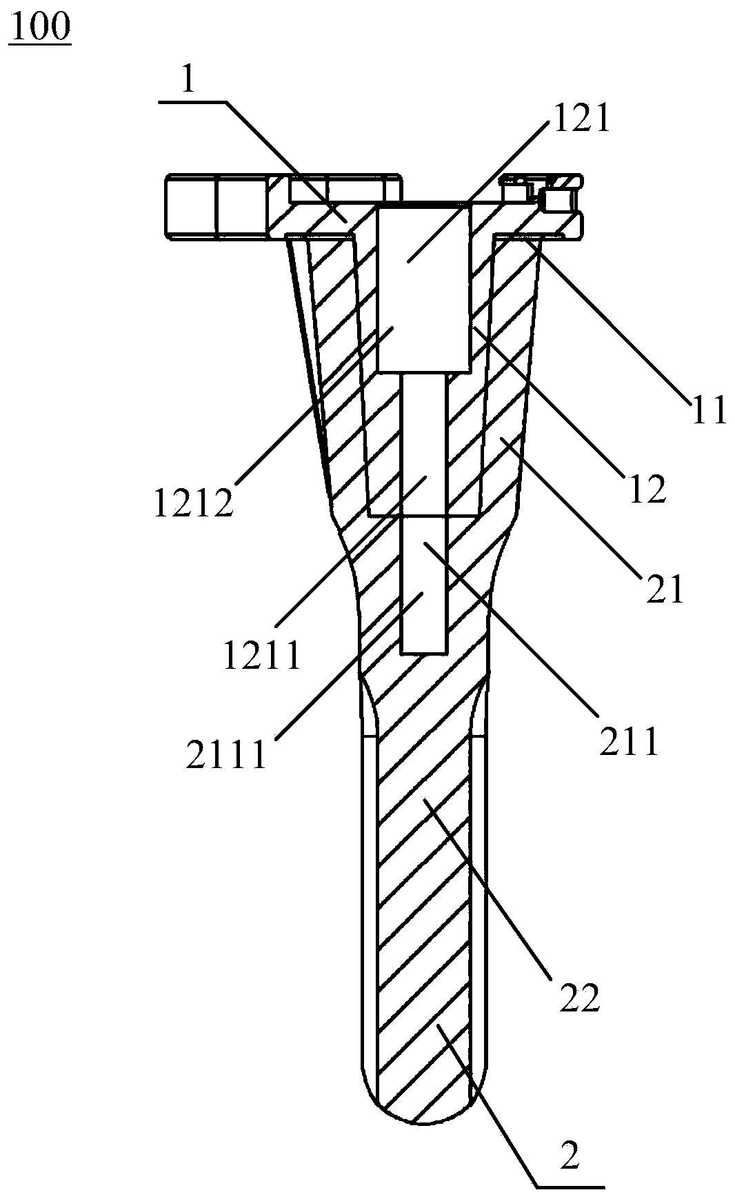
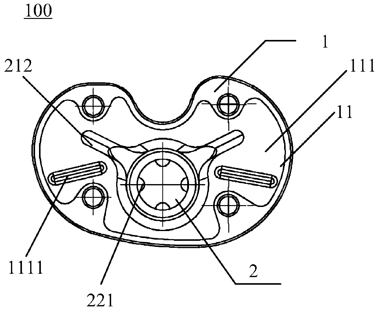
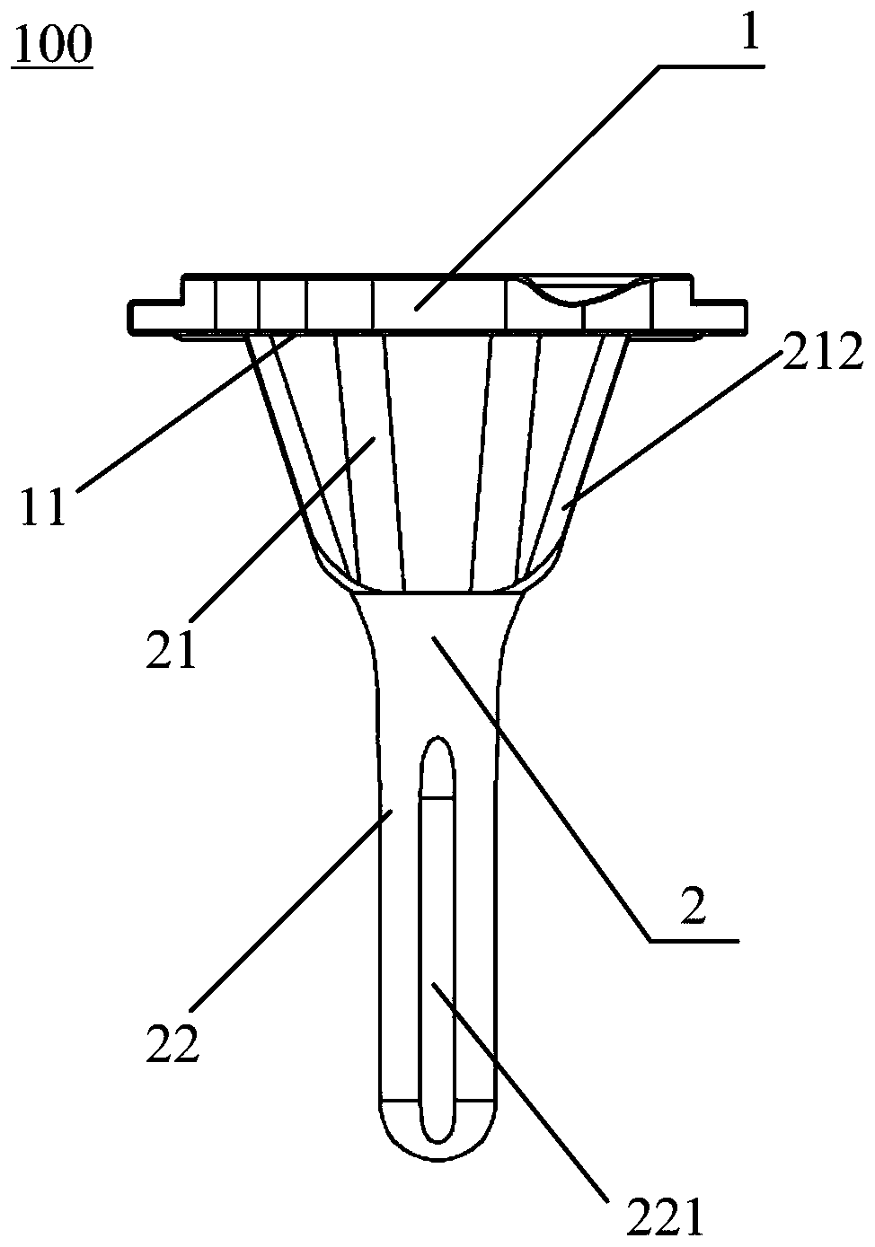
[0039] figure 1 A cross-sectional view of the structure of a first embodiment of a tibial plateau assembly 100 according to the present invention is shown. Such as figure 1 As shown, the tibial plateau assembly 100 includes: a tibial plateau part 1 and an extension part 2 detachably connected with the tibial plateau part 1 . Wherein, the first plane 11 of the tibial plateau part 1 for connecting with the osteotomy surface of the tibia is formed with a connecting post 12 perpendicular to the first plane 11, and the extension part 2 includes an outer part for being sleeved on the connecting post 12. The sleeve 21 ...


PUM


Abstract

The invention belongs to the field of medical apparatus, and discloses a tibial plateau assembly and a knee joint prosthesis using the tibial plateau assembly. The tibial plateau assembly includes a tibial plateau part and an extension part which is detachably connected with the tibial plateau part, wherein a connection column is formed on a first plane, which is used for being connected with a resected surface of a tibia, of the tibial plateau part and is perpendicular to the first plane; and the extension part includes a sleeving connection cylinder and an extension rod, wherein the sleevingconnection cylinder is used for being connected with the outer surface of the connection column in a sleeving mode, the extension rod is coaxially connected with the sleeving connection cylinder, andthe sleeving connection cylinder can rotate relative to the connection column and be fixed, so that rotation positions of the tibial plateau part relative to the extension part are adjusted and fixed. By adopting the tibial plateau assembly, loosening risks of a tibial plateau support can be effectively reduced, and meanwhile the universality of the tibial plateau support is enhanced.

Description

technical field [0001] The invention belongs to the field of medical devices, in particular to a tibial plateau component and a knee joint prosthesis using the same. Background technique [0002] A knee prosthesis is a surgical implant used to replace the knee joint. It is used for surface knee replacement surgery of artificial knee joint, which treats the damaged knee joint and replaces it with a knee joint prosthesis. The existing knee joint prosthesis structure mainly includes: a femoral condyle for connecting with the femur of the human body, a tibial plateau support for connecting with the tibia of the human body, and a tibial plateau pad between the femoral condyle and the tibial plateau support. Specifically, one side of the tibial platform support is used to cover the osteotomy plane of the tibia, and the other side opposite to this side is used to connect the fixed platform pad. [0003] Currently, knee prostheses are widely used in knee replacement surgery. Howe...

Claims


Application Information

Patent Timeline
Patent Type & Authority Applications(China)
IPC IPC(8): A61F2/38
CPCA61F2/3836A61F2/389
Inventor 周勇刚史春宝王帅解凤宝
Owner BEIJING CHUNLIZHENGDA MEDICAL INSTR
Learn More