Welding device for bypass valves of lower end covers of filter elements of filters

A welding device and bypass valve technology, applied in auxiliary devices, welding equipment, welding equipment and other directions, can solve the problems of poor quality, low welding efficiency of filter bypass valve and lower end cover, etc., and achieve good product quality, The effect of high production efficiency

Active Publication Date: 2020-02-14
SIXIAN TENGMA AUTO PARTS CO LTD
View PDF11 Cites 0 Cited by
  • Summary
  • Abstract
  • Description
  • Claims
  • Application Information

AI Technical Summary

Problems solved by technology

[0003] The technical problem to be solved by the present invention is: the technical problem of low welding efficiency and poor quality of the filter bypass valve and the lower end cover in the prior art

Method used


Image

  • Welding device for bypass valves of lower end covers of filter elements of filters
  • Welding device for bypass valves of lower end covers of filter elements of filters
  • Welding device for bypass valves of lower end covers of filter elements of filters

Examples


Embodiment 1

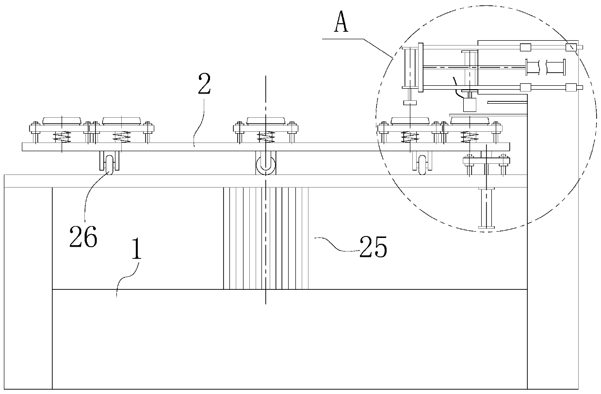
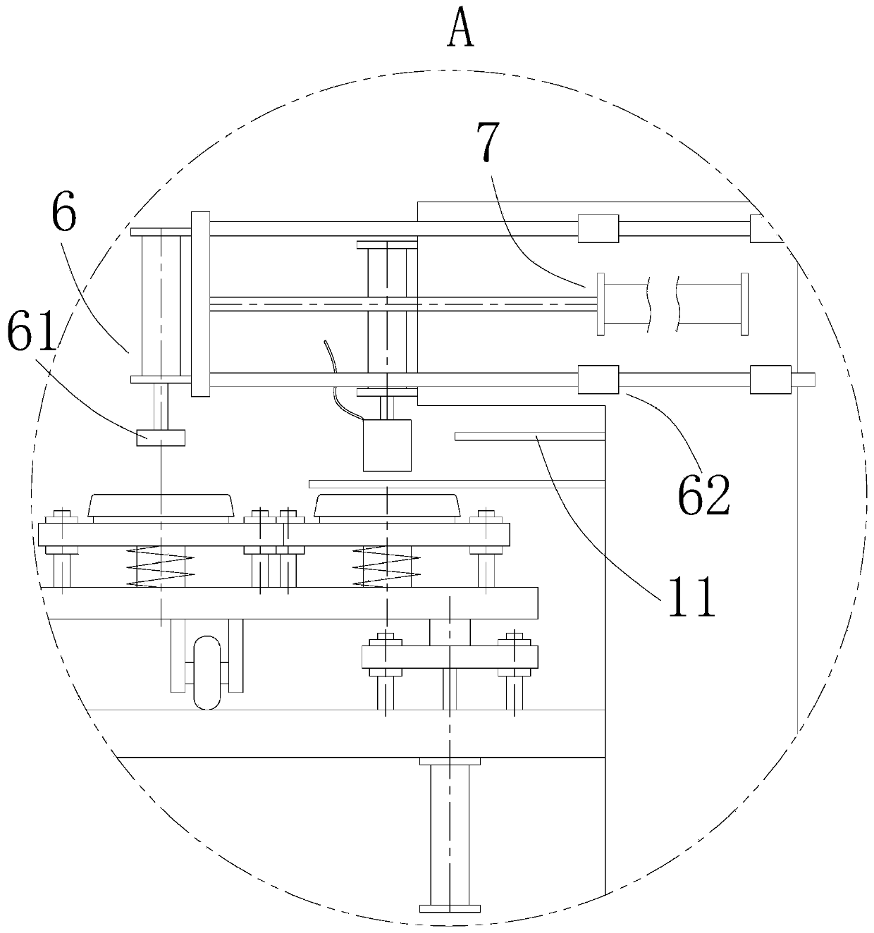
[0049] Such as Figure 1-4 As shown, a filter element lower end cover bypass valve welding device includes a frame 1, a turntable 2, a bypass valve 3, a lower end cover 4, a first lifting mechanism 5, a second lifting mechanism 6, and a lateral drive mechanism 7 ,control unit.

[0050] In this embodiment, the main function of the frame 1 is to provide installation positions for the rest of the components. The frame 1 is not limited to a specific shape, as long as it can meet the requirements of installing and matching each component, and realize the corresponding functions. , in order to avoid the frame 1 from covering the parts that need to be clearly shown, the shape of the frame 1 in the figure is not completely drawn.

[0051] The control unit in this embodiment adopts PLC, which is an existing technology, and those skilled in the art can program it according to actual needs to realize the control function described in this embodiment.

[0052] Such as figure 1 As shown...

Embodiment 2

[0061] The difference between this embodiment and Embodiment 1 is:

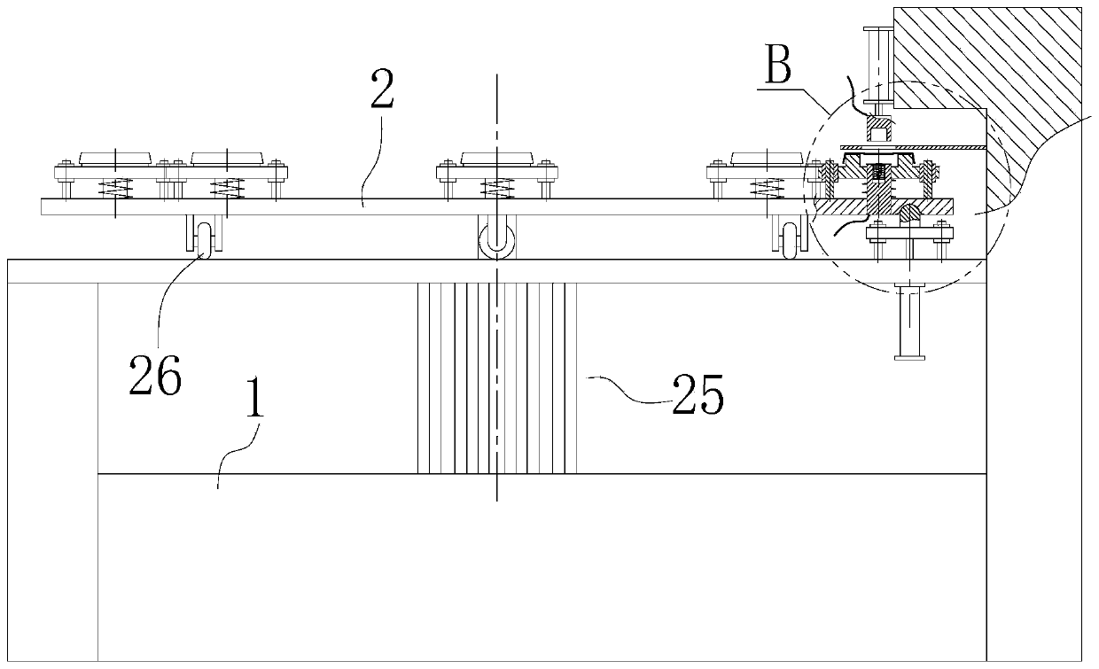
[0062] Such as Figure 4 As shown, the frame 1 is also provided with a turntable positioning mechanism 8 for limiting the rotation of the turntable 2. The turntable positioning mechanism 8 includes a positioning column 81 and a positioning column driving mechanism 82. matching positioning holes, and each column 21 corresponds to a positioning hole, the positioning column 81 is arranged on the movable end of the positioning column drive mechanism 82, when the turntable 2 drives the bypass valve 3 and the lower end cover 4 to a specific position, the positioning The column driving mechanism 82 drives the positioning column 81 to extend into the positioning hole to realize positioning. The positioning column driving mechanism 82 adopts a cylinder or a linear motor.

[0063] Such as Figure 4 As shown, it also includes a positioning plate 84 that is vertically slidably installed on the frame 1 through a third g...


PUM


Abstract

The invention discloses a welding device for bypass valves of lower end covers of filter elements of filters. The welding device comprises a rack, a rotating disk and a control unit; stand columns areevenly arranged on the rotating disk and are sleeved with lower end cover placing pieces; elastic bodies capable of supporting the lower end cover placing pieces are arranged between the lower end cover placing pieces and the rotating disk; the welding device further comprises a first lifting mechanism arranged on the rack; second electrodes of at least one welding machine are arranged at the moving end of the first lifting mechanism; each second electrode is located above the corresponding lower end cover on the corresponding lower end cover placing piece; a suction block is arranged at themoving end of a second lifting mechanism at the discharging station; the second lifting mechanism is connected to the moving end of a transverse driving mechanism; a notch facing the suction block isarranged on a first baffle; the bypass valves moving transversely and the lower end covers are inserted below the notch of the first baffle, the suction block moves upwards, and the bypass valves andthe lower end covers which are welded together fall. The welding device has the advantages that the production efficiency is relatively high, and the product quality is relatively high.

Description

technical field [0001] The invention relates to the field of filter production, in particular to a welding device for a bypass valve of a lower end cover of a filter element. Background technique [0002] A filter refers to an accessory that filters impurities or gases through filter paper. Generally refers to the car filter, which is an accessory of the engine. According to different filtering functions, it is divided into: oil filter, fuel filter (gasoline filter, diesel filter, oil-water separator, hydraulic filter), air filter, air conditioning filter, etc. The engine has three types of filters: air, oil, and fuel, generally called "three filters", plus an air conditioning filter, commonly known as four filters. They are respectively responsible for the lubrication system, the medium in the combustion system, the engine intake system, and the filtration of the cabin air circulation system. For example, the Chinese utility model patent with application number 201520813...

Claims


Application Information

Patent Timeline
Patent Type & Authority Applications(China)
IPC IPC(8): B23K31/02B23K37/047
CPCB23K31/02B23K37/047
Inventor 马训江张海波
Owner SIXIAN TENGMA AUTO PARTS CO LTD
Why Eureka
Try Eureka