
Pulverized coal bunker provided with discharging and weighing device and feeding fluidization system

A weighing device and pulverized coal bunker technology, applied in the field of pulverized coal bins, can solve the problems of eddy current return pulverized coal weighing, inability to provide fuel stably, poor fluidization, etc., to facilitate material flow and injection The effect is uniform and effective, and the effect of improving the activity of lime

Pending Publication Date: 2020-02-14
ACRE COKING & REFRACTORY ENG CONSULTING CORP DALIAN MCC
View PDF0 Cites 0 Cited by
  • Summary
  • Abstract
  • Description
  • Claims
  • Application Information

AI Technical Summary

Problems solved by technology

[0004] The invention provides a pulverized coal bin equipped with a discharge and weighing device and a feed fluidization system, which can solve the problem of easy blockage and poor fluidization of coal powder during storage, discharge, transportation and weighing in the bin. Good, vortex return material and inaccurate coal powder weighing, can not provide fuel to the lime shaft kiln combustion system stably, meet the technological requirements of the lime shaft kiln combustion system, improve the heating uniformity of the kiln materials and finished products, and benefit Reduce the fluctuation of finished product quality and improve the quality of finished product

Method used


Image

  • Pulverized coal bunker provided with discharging and weighing device and feeding fluidization system
  • Pulverized coal bunker provided with discharging and weighing device and feeding fluidization system
  • Pulverized coal bunker provided with discharging and weighing device and feeding fluidization system

Examples


Embodiment Construction

[0033] The specific embodiment of the present invention will be further described below in conjunction with accompanying drawing:

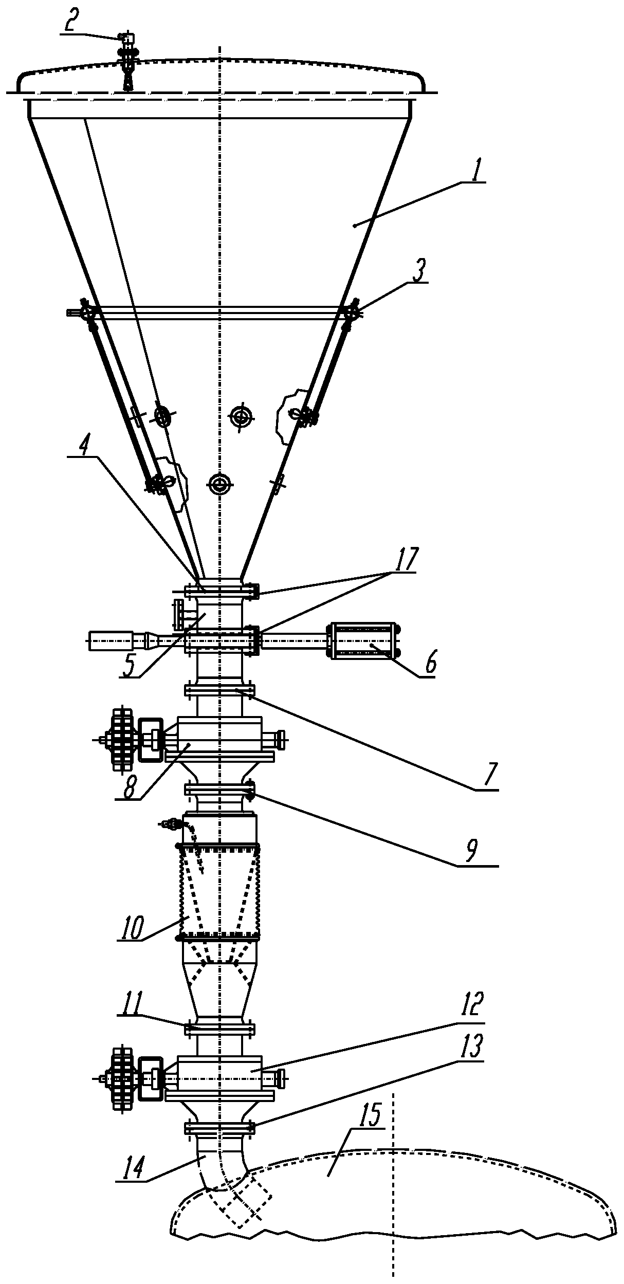
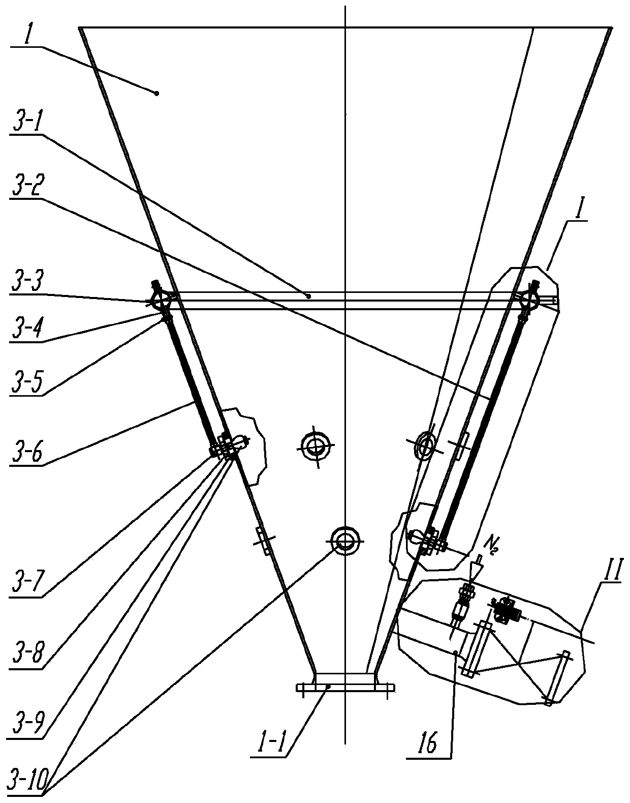
[0034] Such as figure 1As shown, a pulverized coal bunker configured with a discharge and weighing device and a feed fluidization system according to the present invention includes a pulverized coal bunker. Pulverized coal outlet 1-1; also includes annular injection gas supply device 3, fluidization device 10 and powder weighing device 15; said conical hopper 1 is provided with annular injection gas supply device 3 and inlet pipeline 16; The pulverized coal discharge port 1-1 is sequentially connected to the pneumatic gate valve 6, the electric cut-off sealing valve 1 8, the fluidization device 10, the electric cut-off sealing valve 2 12 and the powder weighing device 15, and the pulverized coal discharge port 1 Between -1 and the pneumatic gate valve 6, between the pneumatic gate valve 6 and the electric cut-off sealing valve 8, between the elec...


PUM


Abstract

The invention relates to a pulverized coal bunker provided with a discharging and weighing device and a feeding fluidization system. The pulverized coal bunker comprises a pulverized coal bunker body,an annular injection gas supply device, a fluidization device and a powder weighing device. A conical hopper is arranged on the bottom of the pulverized coal bunker body, the annular injection gas supply device and an inlet pipeline are arranged on the conical hopper, a pulverized coal discharging opening is sequentially connected with a pneumatic gate valve, a first electric cut-off seal valve,the fluidization device, a second electric cut-off seal valve and the powder weighing device, the pulverized coal discharging opening and the pneumatic gate valve are connected through a flange, the pneumatic gate valve and the first electric cut-off seal valve are connected through a flange, the first electric cut-off seal valve is connected with the fluidization device through a flange, the fluidization device is connected with the second electric cut-off seal valve through a flange, and an inlet pipeline serves as a channel of nitrogen injection and large block manual treatment. The problems that in the storage, discharging, conveying, and weighing process of pulverized coal in the bunker, blockage is prone to happening, fluidization is poor, vortex return is generated, weighing of pulverized coal is not accurate, and fuel cannot be stably provided for a lime shaft-kiln combustion system are solved.

Description

technical field [0001] The invention relates to the technical field of pulverized coal conveying and feeding in a large lime shaft kiln, in particular to a pulverized coal bin equipped with a discharge and weighing device and a fluidized feeding system. Background technique [0002] When the combustion system of the lime shaft kiln uses pulverized coal as fuel, a pulverized coal bin is required as an intermediate storage tool, and the supply of pulverized coal is controlled by a pulverized coal weighing device, and then the pulverized coal weighed is weighed by the pulverized coal weighing device. The same amount is provided to the burners of multiple evenly distributed combustion systems, so as to ensure that the lime in each part of the lime shaft kiln is burned uniformly, and to avoid or reduce the phenomenon of overburning and raw burning of quicklime. [0003] The currently commonly used connection structure between the pulverized coal bin and the pulverized coal weighi...

Claims


Application Information

Patent Timeline
IPC IPC(8): B65D88/28B65D88/70B65D90/22B65G65/40B65G69/06B65G69/00C04B2/10F23K3/02
CPCB65D88/28B65D88/70B65D90/22B65G65/40B65G69/00B65G69/06C04B2/10F23K3/02F23K2203/103F23K2203/104F23K2203/201
Inventor 夏敬山潘中伟杨耕桃
Owner ACRE COKING & REFRACTORY ENG CONSULTING CORP DALIAN MCC
Learn More