Hollow stabilizer bar producing process

A production process and stabilizer bar technology, applied in the field of hollow stabilizer bar production process, can solve the problems of high labor intensity, affecting bushing press-fitting, low production efficiency, etc., to reduce operation intensity, reduce operators, and simplify production process. Effect

Active Publication Date: 2020-02-18
ANQING HUITONG AUTOMOTIVE PARTS
View PDF13 Cites 0 Cited by
  • Summary
  • Abstract
  • Description
  • Claims
  • Application Information

AI Technical Summary

Problems solved by technology

The entire process steps are cumbersome, and many people are required to participate in the production, and the manual labor intensity is high, time-consuming and laborious, the production efficiency is not high, and the production cost is high.
[0003] With the development of production automation and the cost reduction requirements of customers, it is urgent to improve the current hollow stabilizer bar production process, thereby improving production efficiency, reducing labor costs, and maximizing product profits; One end of the flattening operation is performed, and then the other end is flattened after one period of flattening. The flattening process is cumbersome, and the flatness of the two ends of the two flattenings cannot be guaranteed, resulting in an increase in the reject rate. When the end is drilled, due to the hollow structure, there will be a certain degree of instability during the drilling process, and the drilling quality is not good, which will affect the later press-fitting of the bushing

Method used


Image

  • Hollow stabilizer bar producing process
  • Hollow stabilizer bar producing process
  • Hollow stabilizer bar producing process

Examples


Embodiment Construction

[0038] See attached picture.

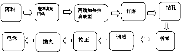
[0039] A hollow stabilizer bar production process is characterized in that it specifically includes the following steps:

[0040] (1), blanking

[0041] The qualified hollow metal pipe raw material is positioned at the positioning end, and then the raw material is hoisted to the machine station using a crane, and cut to the designed length on the circular sawing machine. The sawn material is removed, transported to a special trolley and stacked Neatly ready for use;

[0042] (2) Electric welding filled inner sleeve

[0043] Insert the filling inner sleeve at both ends of the blanking rod, and ensure that the end face of the filling inner sleeve and the end face of the rod body are slightly inward by 2 to 3 mm, and then fix the filling inner sleeve by spot welding on each end face;

[0044] (3) Heating and flattening at both ends

[0045] Put both ends of the rod body with the filling inner sleeve after step (2) into the induction coil at the same time

[004...


PUM


Abstract

The invention discloses a hollow stabilizer bar producing process. The process specifically includes the following steps of firstly, performing blanking; secondly, performing electric welding on filling inner sleeves, inserting the filling inner sleeves in the two ends of a blanked bar correspondingly, ensuring that the end faces of the filling inner sleeves are slightly 2-3 mm inward than the endfaces of a bar body, and then fixing the filling inner sleeves to the end faces through a spot welding method; thirdly, performing heating, flattening and forming on the two ends, putting the two ends, provided with the filling inner sleeves in the second step, of the bar body into an induction coil to be heated at the same time, transferring the heated workpiece onto a flattening and forming device at a flattening station, and performing extrusion forming on the two ends of the workpiece at the same time; fourthly, performing grinding; fifthly, performing drilling; sixthly, performing bending; seventhly, performing tempering; eighthly, performing correcting; ninthly, performing shot blasting; and tenthly, performing electrophoresis. The process is reasonable in step design, the whole production process is simplified, operators are reduced, operation intensity is lowered, and production efficiency is improved; and by performing flattening on the two ends at the same time, it can be ensured that the two ends are consistent in flatness, and the product quality is ensured.

Description

Technical field [0001] The invention relates to the field of hollow stabilizer bar production and processing, and mainly relates to a hollow stabilizer bar production process. Background technique [0002] The traditional hollow stabilizer bar production process is: blanking → pipe bender bending → sawing material at one end (the two ends are equal arm length) → the other end sawing material (equal arm length at both ends) → tempering → heating and flattening at one end → the other end Heating flattening→drilling→boring→correction→shot blasting→spraying. The whole process steps are cumbersome, require a large number of personnel involved in the production, and the manual labor is intensive, time-consuming, laborious, low production efficiency, and high production costs. [0003] With the development of production automation and the requirements of customers to reduce costs, there is an urgent need to improve the current hollow stabilizer bar production process, thereby improving p...

Claims


Application Information

Patent Timeline
IPC IPC(8): B23P15/00
CPCB23P15/00
Inventor 徐天石
Owner ANQING HUITONG AUTOMOTIVE PARTS
Why Eureka
Try Eureka