Pi-energy fuel catalyst core

A fuel catalytic core and fuel technology, which is applied to combustion engines, internal combustion piston engines, combustion air/combustion-air treatment, etc., can solve the problems of high use cost, affecting the life of fuel injectors, and interfering with the work of electronic components, etc. Improve the utilization rate of combustion power, reduce exhaust pollutant emissions, and improve the effect of fuel catalysis

Pending Publication Date: 2020-02-18
吴俊明
View PDF7 Cites 0 Cited by
  • Summary
  • Abstract
  • Description
  • Claims
  • Application Information

AI Technical Summary

Problems solved by technology

However, for the first two catalytic methods, the oil supply system of the original vehicle needs to be changed during installation, which is likely to cause driving failure and safety hazards, and the service life is short, generally about 3 months to 2 years
[0003] The first one is to use only the form of magnetization to promote smaller fuel molecular clusters. This structure has some fuel-saving effects, but it is unsatisfactory, and the use of general magnets will reduce the effect by half and shorten the life of the engine under high temperature.
At the same time, the magnetic field of the magnet will also interfere with the work of other electronic components, and the oil supply system of the original vehicle must be changed during installation, which may easily cause driving failures and potential safety hazards
[0004] The second type adopts aluminum can ceramic bead structure or honeycomb filter core structure, which is catalyzed by engine vibration and heat to dissolve solid additives. This structure has a certain lifting effect, but due to vibration, ceramic particles will produce powder, which may affect the fuel injector. Life, short life and the reduction of additives, the effect is also reduced or invalid, although some do not indicate the use of solid additives, but basically there are, the general effect is about 3 months to 2 years
Moreover, the oil supply system of the original vehicle must be changed during installation, which may easily cause traffic failure and potential safety hazards.
[0005] The third method is to add solid tablets or liquid directly into the fuel tank from the filler port to directly dissolve the solid or liquid catalyst. This method has a certain improvement effect, but it will produce stabilizer powder or other impurities in the catalyst, which may affect The service life of the fuel injector, and the extra work of adding it every time you refuel, which makes it more troublesome to use, and the cost of use is relatively high, resulting in no obvious economic benefits, and users tend to forget to add it or are unwilling to use it

Method used


Image

  • Pi-energy fuel catalyst core
  • Pi-energy fuel catalyst core
  • Pi-energy fuel catalyst core

Examples


Embodiment Construction

[0019] The present invention will be described below with reference to specific examples. Those skilled in the art can understand that these examples are only used to illustrate the present invention and do not limit the scope of the present invention in any way.

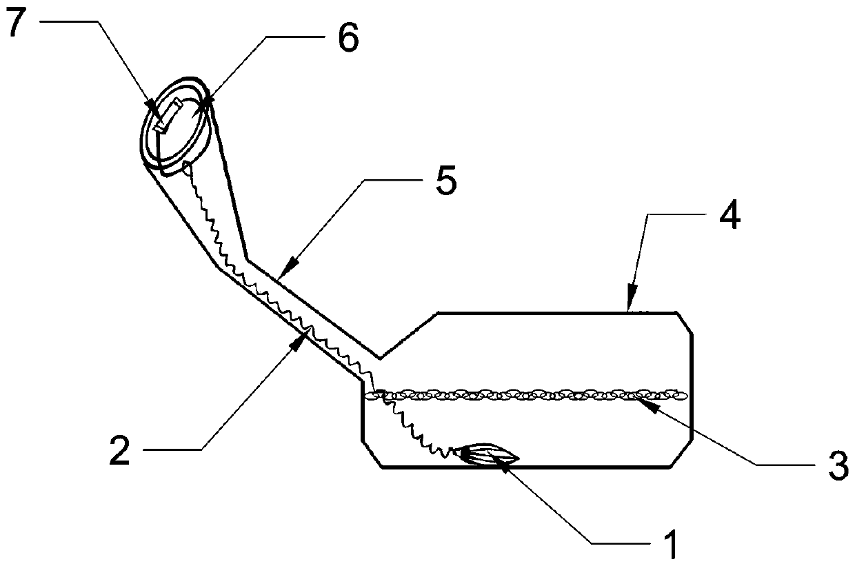
[0020] A π-energy fuel catalyst core, such as Figure 1 to Figure 3 As shown, it includes a crystal and a carrier; the material of the carrier is fluorine rubber; the carrier adopts an ellipsoid-shaped 8-piece sector structure; the crystal adopts various technical elements such as high-energy composite materials and rare metals, and produces 7 kinds of high-frequency vibrations of different frequencies Energy crystals, 7 different crystals can produce far infrared rays and near infrared rays at the same time, all of which are permanent carriers produced by physical endogenous sources; the crystals are vertically implanted on the carrier to form a fuel catalytic core (1);

[0021] The fuel catalytic core (1) is plac...


PUM


Abstract

The invention provides a pi-energy fuel catalyst core. The pi-energy fuel catalyst core comprises crystals and a carrier. The carrier is made of fluorelastomer and is of an ellipsoid eight-sector structure. Various technical elements like high energy composite materials and rare metals are adopted in the crystals. Seven types of the high-frequency vibration energy crystals at different frequenciesare manufactured. The seven types of the different crystals can produce far infrared rays and near infrared rays at the same time, and the far infrared rays and the near infrared rays all belong to permanent carriers produced through physical endogenous factors. The crystals are vertically implanted onto the carrier, so that a fuel catalyst core body is formed, and the service life of the fuel catalyst core body is longer than ten years. The fuel catalyst core body is connected with a built-in clamping ring of an oil tank oil filler and a stainless steel chain, and thus the fuel catalyst corebody can be taken out for replacement conveniently or be used for other purposes. A telescopic clamping ring is arranged on the inner wall of the oil filler. The pi-energy fuel catalyst core is simple in structure and convenient to install and use, and due to the fuel catalyst core, other former engine structures like a former engine circuit system, an oil supply system, a fuel spray nozzle system and an air throttle system do not need to be changed.

Description

technical field [0001] The invention belongs to the technical field of fuel catalytic devices, and in particular relates to a π-energy fuel catalytic core. Background technique [0002] There are several common fuel catalysts currently on the market: several common fuel catalyst methods currently on the market: 1. Using magnetization to catalyze fuel; 2. Using aluminum can ceramic bead structure or honeycomb filter core structure to release solid Catalyst to catalyze the fuel; 3. Use solid tablets or liquid catalysts to add directly from the filler port to the fuel tank, such as conventional fuel catalysis methods. However, for the first two catalytic methods, the oil supply system of the original vehicle needs to be changed during installation, which is likely to cause driving failure and potential safety hazards, and the service life is short, generally about 3 months to 2 years. [0003] The first is to use only the form of magnetization to promote smaller molecular clus...

Claims


Application Information

Patent Timeline
IPC IPC(8): F02M27/00F02M27/06F02M27/02
CPCF02M27/00F02M27/06F02M27/02Y02T10/12
Inventor 吴俊明
Owner 吴俊明
Why Eureka
Try Eureka