A rapid cooling recovery device for reaction solvent

A technology of rapid cooling and reaction solvent, applied in separation methods, dispersed particle separation, chemical instruments and methods, etc., can solve problems such as incomplete cooling and recovery, and achieve the effect of improving cooling effect, recycling water source, and improving cooling effect.

Active Publication Date: 2021-08-06
LEIYANG JINYUE SCI & TECH DEV
View PDF31 Cites 0 Cited by
  • Summary
  • Abstract
  • Description
  • Claims
  • Application Information

AI Technical Summary

Problems solved by technology

[0004] A reaction solvent rapid cooling and recovery device in the above patent has the following disadvantages: when the device is in use, the gas containing solvent in chemical production enters the device, and the gas flow rate is too fast, which may easily lead to incomplete cooling and recovery.

Method used


Image

  • A rapid cooling recovery device for reaction solvent
  • A rapid cooling recovery device for reaction solvent
  • A rapid cooling recovery device for reaction solvent

Examples


Embodiment 1

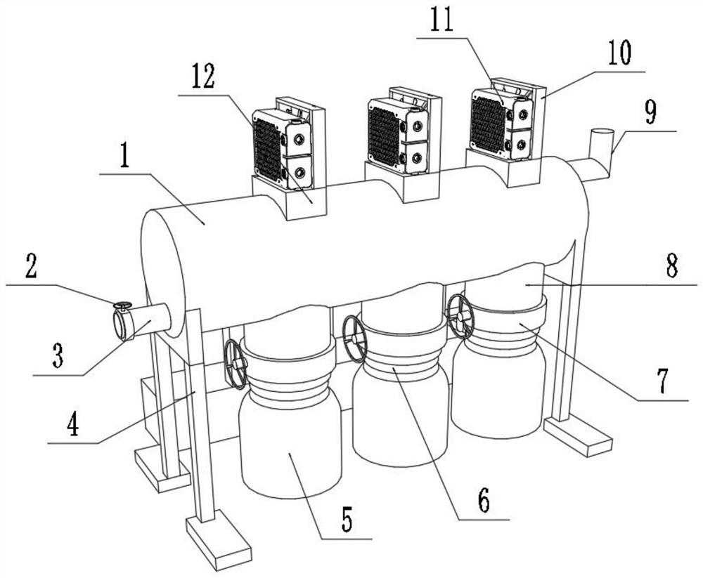
[0028] A reaction solvent rapid cooling recovery device, such as Figure 1-4 As shown, including the tank body 1 and the water tank 20, both sides of the bottom end of the tank body 1 are welded with brackets 4;

[0029] The bottom of one end of the tank body 1 is welded with an air inlet pipe 3, and the top of the other end of the tank body 1 is welded with an exhaust pipe 9. The outer wall of the air inlet pipe 3 is clamped with a first valve 2 through a clamp, and the air inlet pipe 3 is connected to a solvent-containing The chemical gas is discharged through the exhaust pipe 9 after cooling and recovery;

[0030] Wherein, the bottom end of the bottom of the tank body 1 is welded with several feeding pipes 8, the outer wall of the feeding pipe 8 is clamped with a second valve 7 through a clamp, and the bottom end of the feeding pipe 8 is welded with a connector 6, The bottom end of the connector 6 is threadedly connected to the collection tank 5; the tank body 1 is provide...

Embodiment 2

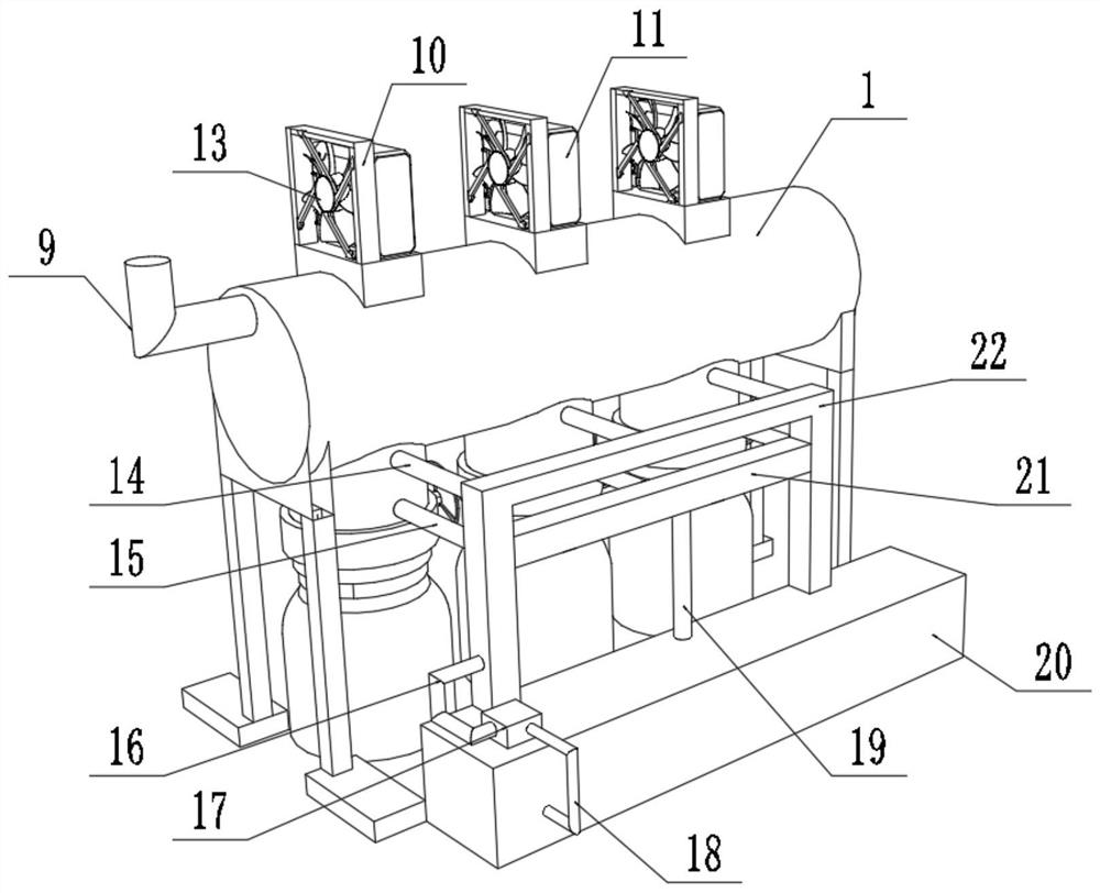
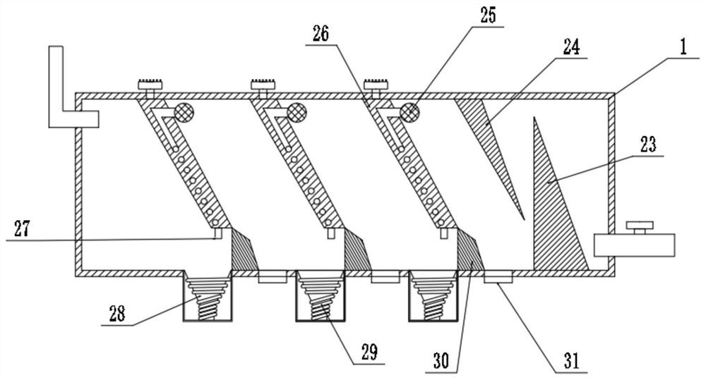
[0036] A reaction solvent rapid cooling recovery device, such as figure 2 and image 3 As shown, in order to solve the problem of incomplete cooling; this embodiment makes the following improvements on the basis of embodiment 1: the top of the water tank 20 is provided with a water-cooled driving mechanism, and a bucket body 28 is welded in the feeding pipe 8, and the bucket The outer wall of the body 28 is connected with a spirally distributed condensation pipe 29, and the solvent cooled by the drop pipe 27 is dropped into the bucket body 28 and discharged into the collection tank 5;

[0037] Wherein, the water-cooled drive mechanism includes a water tank 20, a gantry frame 22 and a water pump 17, the water pump 17 is fixed on the top of the water tank 20 by screws, the gantry frame 22 is welded to the top of the water tank 20, and the top of the condensation pipe 29 is welded with an outlet pipe 14, The bottom end of the condensation pipe 29 is welded with a water inlet pipe...


PUM


Abstract

The invention discloses a reaction solvent rapid cooling and recovery device, which relates to the technical field of chemical production; in order to solve the problem that the gas containing solvent enters the device in chemical production, and the gas flow rate is too fast, which may easily lead to incomplete cooling and recovery; specifically includes The tank body and the water tank are welded with brackets on both sides of the bottom end of the tank body, an air intake pipe is welded at the bottom of one end of the tank body, an exhaust pipe is welded at the top of the other end of the tank body, and the outer wall of the air intake pipe is clamped by a clamp. For the first valve, several feeding pipes are welded at the bottom of the bottom of the tank body, the outer wall of the feeding pipe is clamped with a second valve through a clamp, and a connector is welded at the bottom of the feeding pipe. In the present invention, by setting the air guide cooling mechanism, the first air guide plate and the second air guide plate are combined to form a curved circuit, which can effectively reduce the gas entry speed, thereby improving the cooling effect of the gas on the cooling plate, and avoiding the air speed caused by the rapid wind speed. Incomplete gas refrigeration occurs.

Description

technical field [0001] The invention relates to the technical field of chemical production, in particular to a reaction solvent rapid cooling recovery device. Background technique [0002] In recent years, with the rapid development of my country's chemical industry, more and more types of organic solvents are used. Various solvents headed by acetone, such as toluene, xylene and other aromatic solvents, alcohols, esters, methyl ethyl ketone (MEK), isobutyl methyl ketone (MIBK) and other solvents, are used in synthetic fibers and synthetic It is widely used in resin industry, printing industry, paper processing industry and other fields. [0003] After searching, the Chinese patent application number is 201721416358.8, which discloses a rapid cooling and recovery device for reaction solvent, including a cooling tank and a storage tank, and a spiral coil cooling pipe is arranged in the cooling tank. The upper end of the cooling recovery tank is provided with a liquid inlet c...

Claims


Application Information

Patent Timeline
Patent Type & Authority Patents(China)
IPC IPC(8): B01D5/00B01D46/00
CPCB01D5/0006B01D5/0072B01D46/00
Inventor 周新红李泽龙义训坤黄涛
Owner LEIYANG JINYUE SCI & TECH DEV
Why Eureka
Try Eureka