Small pipeline flaring stamping device

A technology of flaring stamping and small pipes, which is applied in the field of stamping devices, can solve the problems of high cost, small pipe damage, and low pass rate, and achieve the effect of low cost, not easy to damage, and high pass rate

Inactive Publication Date: 2020-02-21
FUQUAN DECAI AUTO PART MFG
View PDF0 Cites 2 Cited by
  • Summary
  • Abstract
  • Description
  • Claims
  • Application Information

AI Technical Summary

Problems solved by technology

[0002] Our company is engaged in the production of automobile exhaust pipes, tail throats, general drums, exhaust pipe accessories and other products. During the processing of these products, small pipes need to be flared. However, the existing pipe stamping device has the following technical problems: It is not suitable for stamping and flaring of small pipes, the alignment of the punching head and the pipe is complicated, and the precision is low; the scope of application of the existing pipe stamping device is small, and it is troublesome to replace the punching head for small pipes of different diameters, and the structure is complicated. The cost is high; the existing stamping device is complicated to fix the stamping head during the stamping process, and because the wall of the small pipe is thin, it is easy to cause damage to the small pipe during the process of fixing and stamping the small pipe, and the pass rate is low, resulting in the failure of the small pipe The cost of flaring processing is high, and the fixing and removal of small pipes in flaring processing is complicated, resulting in low efficiency of stamping and flaring processing of small pipes

Method used


Image

  • Small pipeline flaring stamping device
  • Small pipeline flaring stamping device
  • Small pipeline flaring stamping device

Examples


Embodiment Construction

[0024] The present invention will be further described below in conjunction with the accompanying drawings and embodiments, but not as a basis for limiting the present invention.

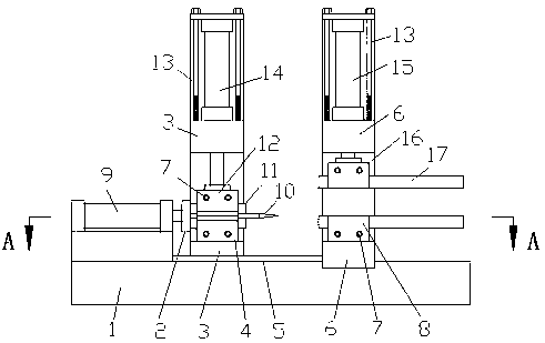
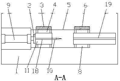
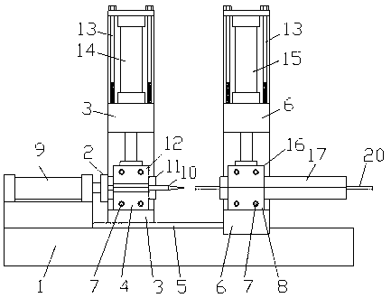
[0025] Example. A small pipe flaring stamping device, constituted as Figure 1-5 As shown, there is a stamping platform 1, a chute 5 is provided on the stamping platform 1, a stamping head fixing table 3 is movably connected to the chute 5, and a stamping cylinder 9 is provided on the stamping platform 1 on the left side of the chute 5, and the punching One end of the cylinder 9 is connected to the punching head fixing table 3 through the connecting block 2, and the punching platform 1 on the right side of the chute 5 is provided with a small pipe fixing table 6; the punching head fixing table 3 is provided with a first punching head fixing block 4. The first punching head fixing block 4 is provided with the second punching head fixing block 12, and the opposite sides of the first punching head fix...


PUM


Abstract

The invention discloses a small pipeline flaring stamping device. The small pipeline flaring stamping device comprises a stamping platform, wherein a sliding groove is formed in the stamping platform;a stamping head fixing table is movably connected to the sliding groove; a stamping air cylinder is arranged on the stamping platform on the left side of the sliding groove; one end of the stamping air cylinder is connected with the stamping head fixing table through a connecting block; a small pipeline fixing table is arranged on the stamping platform on the right side of the sliding groove; a first stamping head fixing block is arranged on the stamping head fixing table; a second stamping head fixing block is arranged on the first stamping head fixing block; and stamping head clamps are oppositely arranged on the opposite sides of the first stamping head fixing block and the second stamping head fixing block. The small pipeline flaring stamping device has the beneficial effects that a stamping head is simple to replace, the stamping head and a small pipeline are aligned and stamped reliably, the application range is large for small pipelines with different calibers, the small pipeline is not prone to damage, the percent of pass is high, the cost is low, the small pipeline is simple to fix and take out in the flaring machining process, the use is convenient, and the machining efficiency is high.

Description

technical field [0001] The invention relates to a stamping device, in particular to a small pipe flaring stamping device. Background technique [0002] Our company is engaged in the production of automobile exhaust pipes, tail throats, general drums, exhaust pipe accessories and other products. During the processing of these products, small pipes need to be flared. However, the existing pipe stamping device has the following technical problems: It is not suitable for stamping and flaring of small pipes, the alignment of the punching head and the pipe is complicated, and the precision is low; the scope of application of the existing pipe stamping device is small, and it is troublesome to replace the punching head for small pipes of different diameters, and the structure is complicated. The cost is high; the existing stamping device is complicated to fix the stamping head during the stamping process, and due to the thin wall of the small pipe, it is easy to cause damage to the...

Claims


Application Information

Patent Timeline
Patent Type & Authority Applications(China)
IPC IPC(8): B21D41/02B21D43/00B21D37/04
CPCB21D37/04B21D41/02B21D43/003
Inventor 邓厚才
Owner FUQUAN DECAI AUTO PART MFG
Why Eureka
Try Eureka