Control apparatus and vehicle drive system

A control device and vehicle technology, applied in the direction of control drive, control system, control device, etc., can solve the problems of increasing the manufacturing cost of wheel speed sensors, increasing the sensor size, and low resolution

Pending Publication Date: 2020-02-21
DENSO CORP
View PDF0 Cites 0 Cited by
  • Summary
  • Abstract
  • Description
  • Claims
  • Application Information

AI Technical Summary

Problems solved by technology

Typically, magnetoresistive elements (MR elements) are used as wheel speed sensors, which have a lower resolution than resolvers
Increasing the resolution of the wheel speed sensor may lead to factors such as increased manufacturing cost or increased sensor size

Method used


Image

  • Control apparatus and vehicle drive system
  • Control apparatus and vehicle drive system
  • Control apparatus and vehicle drive system

Examples


no. 1 example

[0065] The rotating electrical machine of the first embodiment of the present invention is used as, for example, a vehicle power source, that is, a drive source for vehicle travel. Note that the rotary electric machine can be widely used for industrial use, for vehicles, for home appliances, for OA (Office Automation) equipment, for game machines, and the like.

[0066] (Schematic structure of a rotating electrical machine)

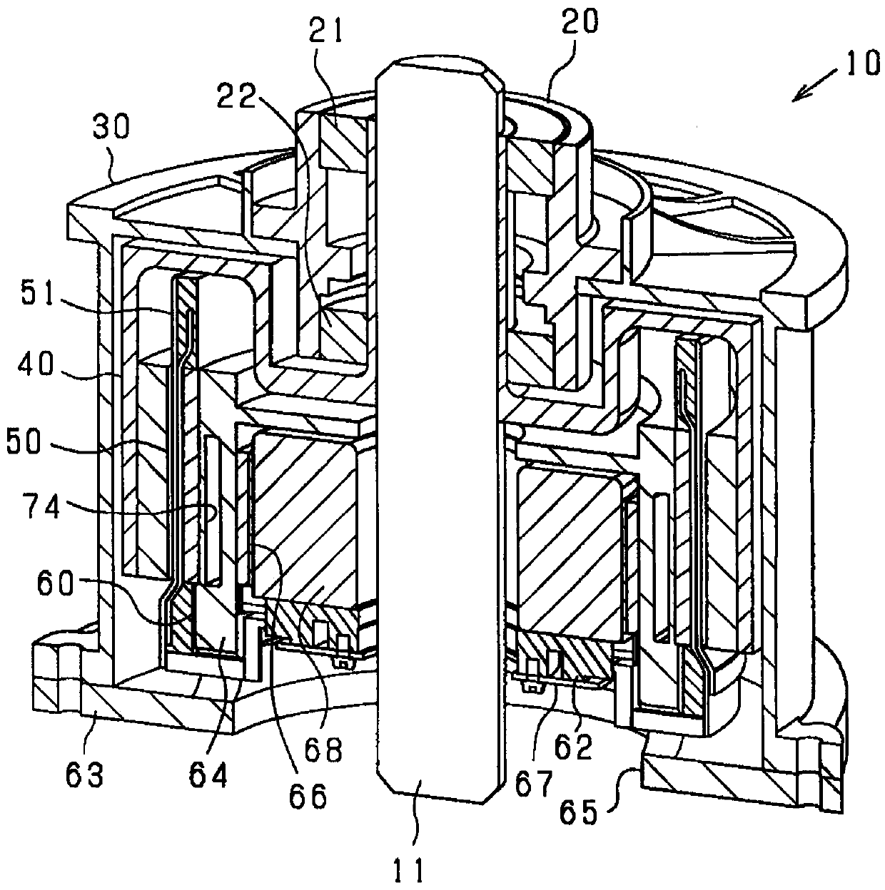
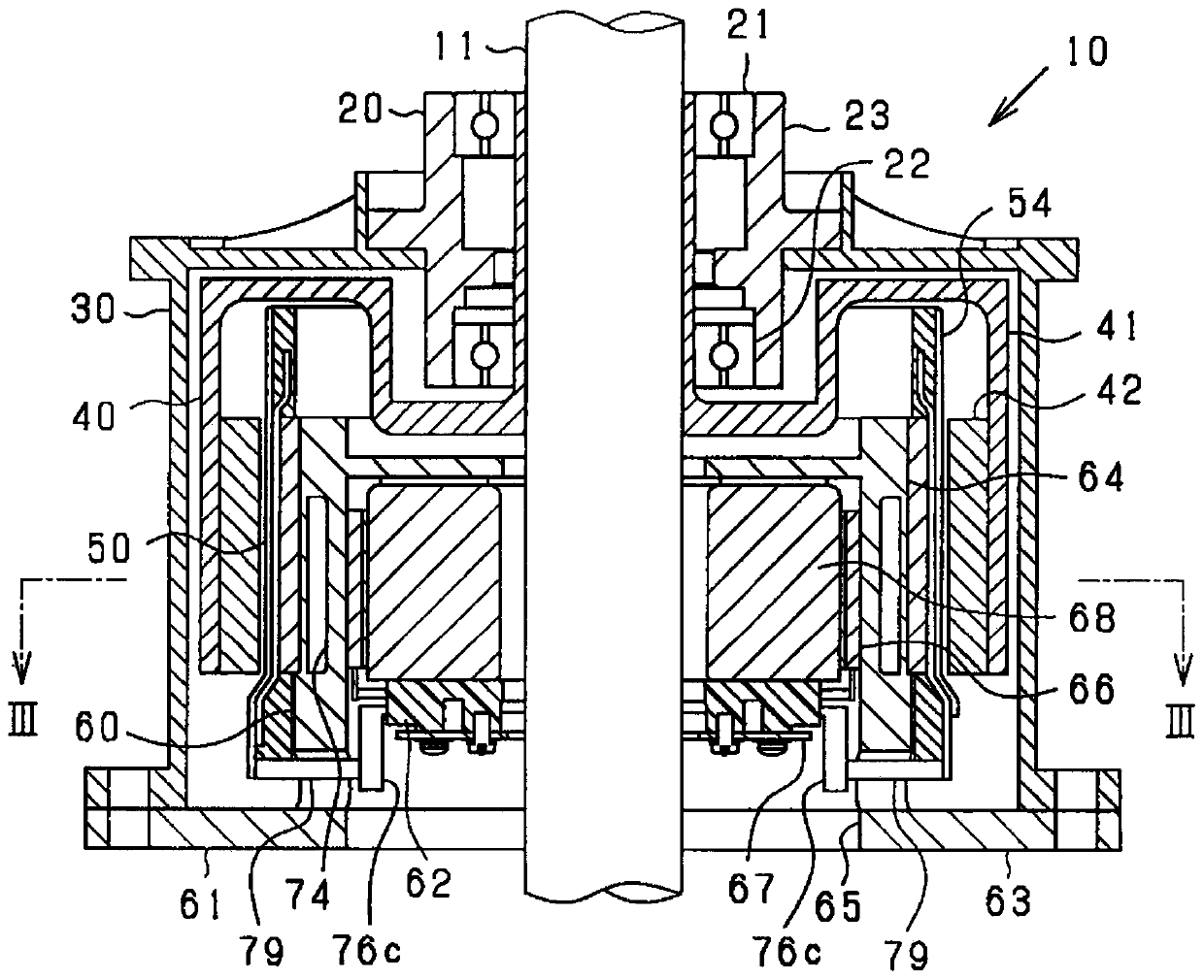
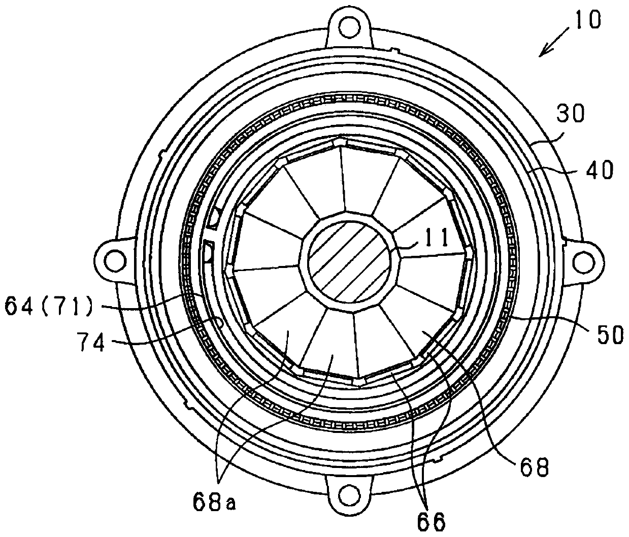
[0067] based on Figure 1 to Figure 8 , a schematic configuration of the rotating electric machine 10 is described. The rotating electrical machine 10 may also be referred to as an electric motor. figure 1 It is a longitudinal cross-sectional perspective view of the rotating electrical machine 10 . figure 2 is a longitudinal sectional view in a direction along the rotating shaft 11 of the rotary electric machine 10 . image 3 is a transverse sectional view (along figure 2 Cross-sectional view of line III-III in). Figure 4 is showing image 3 An ...

no. 2 example

[0214] For this embodiment, reference may be made to the foregoing embodiments. Therefore, descriptions of components common to the rotary electric machine 10 , the vehicle drive system 136 , and the control device 137 shown in the foregoing embodiments are omitted.

[0215] Such as Figure 25 As shown, the rotating electric machine 10 of this embodiment includes a rotation angle sensor 135 . The rotation angle sensor 135 may employ a resolver or a Hall sensor using a Hall element.

[0216] The setting unit 139 of the present embodiment has a plurality of functions in addition to the function of estimating and setting the electrical angle θ from the detection value of the wheel speed sensor 134 . Such as Figure 26 As shown, the setting unit 139 has a function of estimating the wheel speed Nw from the detection value of the rotation angle sensor 135 . Setting unit 139 has a function of detecting whether (i) wheel speed sensor 134 or (ii) rotation angle sensor 135 is abnorm...

no. 3 example

[0238] For this embodiment, reference may be made to the foregoing embodiments. Therefore, descriptions of components common to the rotary electric machine 10 , the vehicle drive system 136 , and the control device 137 shown in the foregoing embodiments are omitted.

[0239] Such as Figure 28 As shown, in this embodiment, four wheels 131 are included in the vehicle. The front wheels 131A at the front of the vehicle are driving wheels, and the rear wheels 131b at the rear of the vehicle are driven wheels. The vehicle is provided with two rotary electric machines 10 each including a corresponding rotation angle sensor 135 . Hereinafter, the first one of the rotating electric machines 10 is also referred to as a (first) rotating electric machine 10a, and the second one of the rotating electric machines 10 is also referred to as a (second) rotating electric machine 10b. In addition, the first one of the rotation angle sensors 135 is also called a first rotation angle sensor 13...


PUM


Abstract

A control apparatus (137) is applied to a vehicle including (i) a rotating electrical machine (10) and (ii) a wheel speed sensor (134) detecting a wheel speed. The rotating electrical machine includes: (i) a slotless stator (50) including a stator winding without slots formed by magnetic teeth; and (ii) a rotor (40), wherein the rotor (40) comprises a magnet unit (42). The control apparatus comprises: (i) a setting circuit (139) which is configured to set a rotation angle of the rotating electrical machine based on an estimated value of the rotation angle which is estimated based on a detection value of the wheel speed sensor; and a drive controller (110) which is configured to control the drive of the rotating electrical machine based on the rotation angle set by the setting circuit.

Description

technical field [0001] The invention relates to a control device and a vehicle drive system. Background technique [0002] Patent Document 1 discloses a technique for detecting the wheel speed of a vehicle using a resolver of a drive motor for vehicle travel instead of a wheel speed sensor. This technology provides a speed reducer between the wheels and the drive motor in order to obtain the output torque required by the vehicle. This technology estimates the wheel speed by multiplying the rotation speed of the drive motor detected by the resolver by the speed reduction ratio depending on the speed reducer. [0003] Patent Document 1: JP 2013-068592 A [0004] There is a difference in the number of revolutions corresponding to the reduction ratio between the drive motor and the wheels. Typically, a magnetoresistive element (MR element) is used as a wheel speed sensor, the resolution of which is lower than that of a resolver. Increasing the resolution of the wheel speed s...

Claims


Application Information

Patent Timeline
Patent Type & Authority Applications(China)
IPC IPC(8): B60L15/20H02K1/14H02K1/27H02K11/33
CPCB60L15/20H02K1/2786H02K1/14H02K11/33B60L2240/423B60L2240/461H02K2213/03H02K21/22H02K3/12H02K1/187H02K7/006B60L2220/46B60L2240/421H02P6/17Y02T10/64Y02T10/72H02P29/0016B60W2720/28B60W10/04
Inventor 石田稔片山直树作石翼高桥裕树
Owner DENSO CORP
Why Eureka
Try Eureka