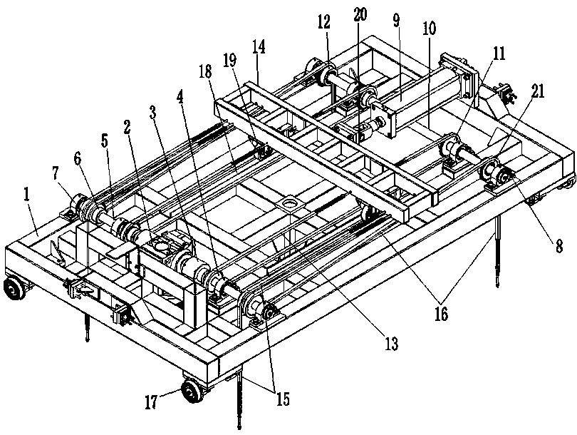
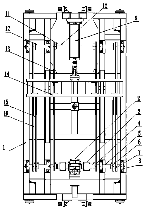
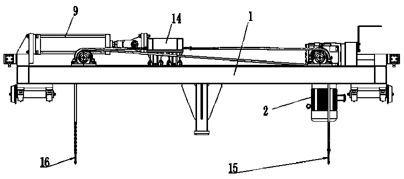
Four-chain synchronous lifting mechanism applied in laser automatic feeding and discharging system

A technology of automatic loading and unloading and synchronous lifting. It is applied in the direction of conveyor objects, transportation and packaging. It can solve the problems of large and cumbersome lifting tooling, imperfect application, and excessive board pairs, so as to achieve stable output force, reduce materials, and ensure The effect of output force

Inactive Publication Date: 2020-02-21
济南新助友联机械科技有限公司
View PDF6 Cites 0 Cited by
  • Summary
  • Abstract
  • Description
  • Claims
  • Application Information

AI Technical Summary

Problems solved by technology

[0006] In the process of metal sheet cutting, the transportation and loading and unloading devices of sheet metal are essential. At present, sheet metal is generally transported in stacks, and the specifications are standard. The sub-size of sheet metal is generally 3000*1500mm, 4000mm *2000mm, 6000*2000mm, when the metal sheet is transported in a single sheet, it is generally carried by manual handling, driving and vacuum suction cup frame for lifting, and automatic loading and unloading system; but these handling methods are not suitable for the metal sheet transportation of the large plate pair Due to the large size of the board and the huge and cumbersome lifting equipment, it cannot be perfectly applied in the advanced process equipment such as automatic loading and unloading. Therefore, an automatic four-chain synchronous lifting mechanism is particularly important.

Method used


Image

  • Four-chain synchronous lifting mechanism applied in laser automatic feeding and discharging system
  • Four-chain synchronous lifting mechanism applied in laser automatic feeding and discharging system
  • Four-chain synchronous lifting mechanism applied in laser automatic feeding and discharging system

Examples


Embodiment Construction

[0043] The following will clearly and completely describe the technical solutions in the embodiments of the present invention with reference to the accompanying drawings in the embodiments of the present invention. Obviously, the described embodiments are only some, not all, embodiments of the present invention.

[0044] In describing the present invention, it should be understood that the terms "upper", "lower", "front", "rear", "left", "right", "top", "bottom", "inner", " The orientation or positional relationship indicated by "outside", etc. is based on the orientation or positional relationship shown in the drawings, and is only for the convenience of describing the present invention and simplifying the description, rather than indicating or implying that the referred device or element must have a specific orientation, so as to Specific orientation configurations and operations, therefore, are not to be construed as limitations on the invention.

[0045] refer to Figure ...


PUM


Abstract

The invention discloses a four-chain synchronous lifting mechanism applied in a laser automatic feeding and discharging system, and belongs to the field of laser cutting conveying mechanism. The four-chain synchronous lifting mechanism applied in the laser automatic feeding and discharging system includes a machine frame, a motor, a driving shaft, a driving chain wheel, a driving shaft lifting chain wheel, a transition chain wheel and a driven shaft. The motor is fixedly connected to the machine frame. The driving shaft is rotationally connected with the machine frame and is connected with a driving end of the motor. The driving chain wheel is fixedly in sleeved connection with the driving shaft. The driving shaft lifting chain wheel is fixedly in sleeved connection with the driving shaft.The transition chain wheel is fixedly in sleeved connection with the driving shaft. The driven shaft is rotationally connected with the machine frame. The four-chain synchronous lifting mechanism applied in the laser automatic feeding and discharging system reduces the material used for lifting tooling of a large surface plate and reduces the production cost of a lifting tool. The lifting area ofthe large surface plate is increased to ensure the production safety. Compared with rack and pinion transmission, the adoption of chain transmission for transmitting power reduces the cost of production; and a condition is provided for automatic machining of the large surface plate.

Description

technical field [0001] The invention relates to the technical field of laser cutting feeding mechanism, in particular to a four-chain synchronous lifting mechanism applied in a laser automatic loading and unloading system. Background technique [0002] With the continuous development and innovation of laser technology at home and abroad, the application of laser cutting technology in actual production is becoming more and more mature, and the cutting of metal materials is even more inseparable from the application of laser cutting technology. There are generally three ways to cut and blank metal sheets : [0003] One is shearing and blanking with a shearing machine. In this blanking method, the cutting surface of the sheet is rough, the incision is uneven, and the shape of the cutting blank is single; [0004] One is plasma cutting blanking, which has a rough cutting surface and can cut sheets with complex shapes; [0005] One is laser cutting blanking. The cutting surface...

Claims


Application Information

Patent Timeline
IPC IPC(8): B65G47/74
CPCB65G47/74
Inventor 李文杰陈博王振孟宪亮
Owner 济南新助友联机械科技有限公司
Why Eureka
Try Eureka