A cam slider plunger pump

A technology of cam slider and plunger pump, which is applied in the field of liquid ultra-high pressure, can solve the problems of easy wear failure rate of connecting rod and crosshead, limited increase of pump output pressure, large volume of ultra-high pressure pump, etc., to avoid positioning Difficulty, improved reliability, and good concentricity

Active Publication Date: 2021-03-02
JIANGSU UNIV OF SCI & TECH
View PDF7 Cites 0 Cited by
  • Summary
  • Abstract
  • Description
  • Claims
  • Application Information

AI Technical Summary

Problems solved by technology

The above-mentioned ultra-high pressure pumps with different structures have limitations. For example, the crankshaft-connecting rod type ultra-high pressure pump has a large volume, and the connecting rod and crosshead are easy to wear and have a high failure rate. The increase of the pump output pressure is limited by the connection between the connecting rod and the crankshaft. Pressure bearing capacity; ball screw type ultra-high pressure pump has limited transmission force

Method used


Image

  • A cam slider plunger pump
  • A cam slider plunger pump
  • A cam slider plunger pump

Examples


specific Embodiment approach 1

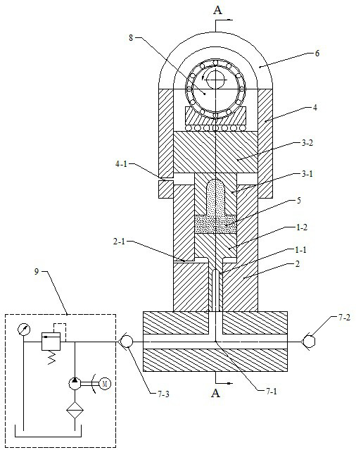
[0019] Such as figure 1 and figure 2 As shown, a cam slider type plunger pump includes a plunger-piston group, a cylinder, a transmission bearing seat 6, a high pressure pump fluid end 7, a cam slider group 8 and a low pressure oil supply system 9; the cylinder The barrel includes a piston cylinder 4 and a plunger cylinder 2, the inner diameter of the piston cylinder 4 is equal to the outer diameter of the plunger cylinder 2, and the side wall of the piston cylinder 4 is provided with a piston cylinder air hole 4-1 , the side wall of the plunger cylinder 2 is provided with a plunger cylinder air hole 2-1. The plunger-piston group is arranged inside the cylinder, including a high-pressure end plunger 1-1, a high-pressure end piston 1-2, a pressure transmission medium 5, a low-pressure end plunger 3-1, and a low-pressure end piston 3 -2, the high-pressure end plunger 1-1 is arranged under the high-pressure end piston 1-2, the low-pressure end plunger 3-1 is arranged under the...

specific Embodiment approach 2

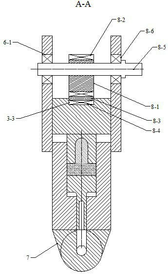
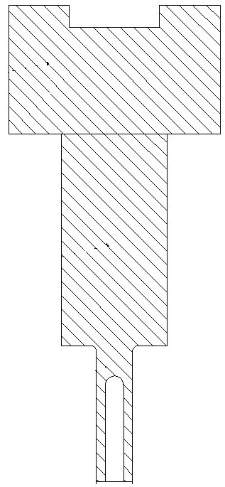
[0022] Such as figure 1 , figure 2 and image 3 As shown, a cam slider type plunger pump includes a stepped shaft, a cylinder, a transmission bearing housing 6, a high-pressure pump fluid end 7, a cam slider group 8 and a low-pressure oil supply system 9; the cylinder includes a piston Cylinder 4 and plunger cylinder 2, the inner diameter of described piston cylinder 4 is equal to the outer diameter of plunger cylinder 2, is provided with piston cylinder air hole 4-1 on the side wall of described piston cylinder 4, described The side wall of the plunger cylinder 2 is provided with a plunger cylinder air hole 2-1. A stepped shaft is arranged inside the cylinder, a slider groove is arranged on the upper part of the stepped shaft, and a cylindrical groove is arranged on the lowermost part of the stepped shaft, and the groove coincides with the central axis of the stepped shaft ; The transmission bearing seat 6 is fixed on the top of the piston cylinder 4, and the cam slider g...


PUM


Abstract

The invention discloses a cam slider type plunger pump, which comprises a plunger-piston group, a cylinder barrel, a transmission bearing seat, a hydraulic end of a high pressure pump, a cam slider group and a low pressure oil supply system. It is composed of three sections of coaxial cylinders in descending order, and the plunger-piston group is arranged inside the cylinder; the transmission bearing seat is fixed on the upper part of the cylinder, and the cam slider group is fixed on On the transmission bearing seat, the cam slider group is in contact with the plunger-piston group; the high-pressure hydraulic end is connected to the lower end of the cylinder, and the low-pressure oil supply system is connected to the high-pressure pump fluid The power ends are connected. The beneficial effects of the invention are: it has the advantages of large supporting force, flexible movement, extremely small friction coefficient and the like.

Description

technical field [0001] The invention belongs to the technical field of liquid ultra-high pressure, in particular to a cam slider plunger pump. Background technique [0002] Ultra-high pressure equipment refers to equipment with a working pressure higher than 100MPa, which is widely used in material processing, chemical synthesis, water jet technology, rock crushing, food processing, equipment cleaning, energy exploration and other fields. The ultra-high pressure pump is the power source of the ultra-high pressure equipment, which determines the technical level of the ultra-high pressure equipment. According to the different motion conversion mechanisms of the power end of ultra-high pressure pumps, ultra-high pumps are mainly divided into: crankshaft-connecting rod type ultra-high pressure pumps, for example, literature: Zhang Guoxian. Ultra-high pressure water hydraulic pumps in shale gas development[J]. Fluid Transmission and Control, 2017(5); ball screw type ultra-high p...

Claims


Application Information

Patent Timeline
Patent Type & Authority Patents(China)
IPC IPC(8): F04B9/04F04B53/16F04B53/14
CPCF04B9/042F04B53/14F04B53/162
Inventor 赵孟军
Owner JIANGSU UNIV OF SCI & TECH
Why Eureka
Try Eureka