Mass transfer method, manufacturing method of display device and display device

A transfer method and display device technology, which can be applied to identification devices, semiconductor/solid-state device manufacturing, instruments, etc., and can solve the problems of low pixel tolerance, difficulty, small pixel size, etc.

Active Publication Date: 2020-02-21
GUANGDONG INST OF SEMICON IND TECH
View PDF6 Cites 19 Cited by
  • Summary
  • Abstract
  • Description
  • Claims
  • Application Information

AI Technical Summary

Problems solved by technology

Whether it is a TV or a mobile phone screen, the number of pixels is quite large, and the size of the pixels is small, and the display product has a low tolerance for pixel errors. A display with "bright spots" or "dark spots" It cannot meet the needs of users, so it is very difficult and complicated to reliably transfer these small pixels to the substrate of the driver circuit and realize the circuit connection

Method used


Image

  • Mass transfer method, manufacturing method of display device and display device
  • Mass transfer method, manufacturing method of display device and display device
  • Mass transfer method, manufacturing method of display device and display device

Examples


Embodiment Construction

[0037] In order to make the purposes, technical solutions and advantages of the embodiments of the present application clearer, the technical solutions in the embodiments of the present application will be clearly and completely described below in conjunction with the drawings in the embodiments of the present application. Obviously, the described embodiments It is a part of the embodiments of this application, not all of them. The components of the embodiments of the application generally described and illustrated in the figures herein may be arranged and designed in a variety of different configurations.

[0038] Accordingly, the following detailed description of the embodiments of the application provided in the accompanying drawings is not intended to limit the scope of the claimed application, but merely represents selected embodiments of the application. Based on the embodiments in this application, all other embodiments obtained by persons of ordinary skill in the art w...


PUM


Abstract

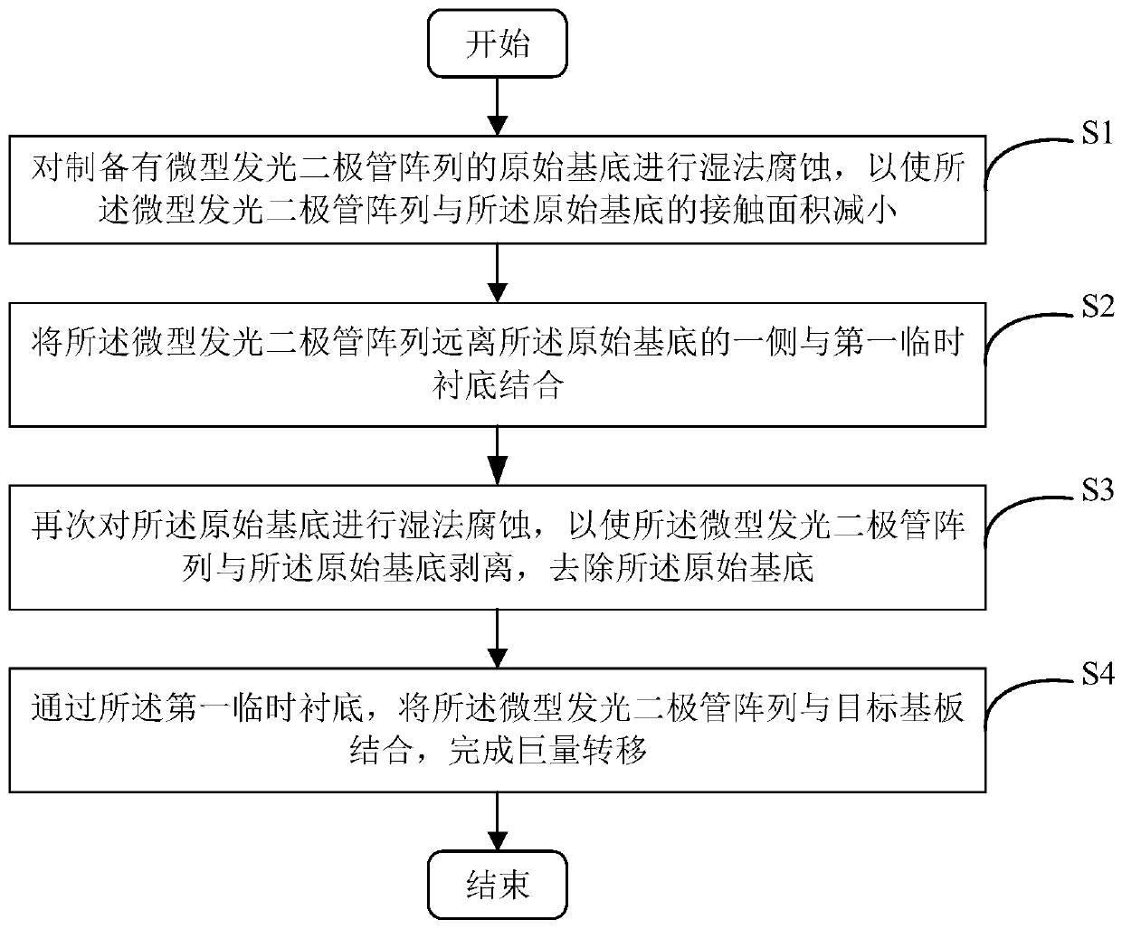
The embodiment of the invention provides a mass transfer method, a manufacturing method of a display device and the display device, and relates to the semiconductor device manufacturing technology field. The mass transfer method comprises the following steps of firstly, carrying out wet etching on an original substrate on which a micro light emitting diode array is manufactured so that a contact area of the micro light emitting diode array and the original substrate is reduced; then, combining one side, far away from the original substrate, of the micro light emitting diode array with a firsttemporary substrate; then, carrying out wet etching on the original substrate again so that the micro light-emitting diode array is separated from the original substrate, and removing the original substrate; and finally, through the first temporary substrate, combining the micro light emitting diode array with a target substrate to complete mass transfer. Therefore, a probability of losses of themicro light emitting diode array during a mass transfer process is reduced by adopting a mode of combining a state of using the temporary substrate to fix the micro light-emitting diode array and successive corrosion, a displacement error is decreased, and a yield is increased.

Description

technical field [0001] The present application relates to the technical field of semiconductor device manufacturing, in particular, to a mass transfer method, a manufacturing method of a display device, and a display device. Background technique [0002] Micro-LED (Micro-LED) is "micro" LED (light-emitting diode). Micro-LED array display is a new display technology, and other display technologies, such as liquid crystal display (Liquid Crystal Display, LCD), organic electromechanical laser display (OrganicLight-Emitting Diode, OLED) Plasma Display (Plasma DisplayPanel, PDP), etc., the core difference is that it uses inorganic LEDs as light-emitting pixels. [0003] The tiny LEDs that have been fabricated need to be transferred to the substrate on which the driving circuit is prepared. Whether it is a TV or a mobile phone screen, the number of pixels is quite large, and the size of the pixels is small, and the display product has a low tolerance for pixel errors. A display w...

Claims


Application Information

Patent Timeline
Patent Type & Authority Applications(China)
IPC IPC(8): H01L21/683H01L27/15G09F9/33
CPCH01L21/6835H01L27/153G09F9/33H01L2221/68386
Inventor 郭婵龚政潘章旭刘久澄龚岩芬王建太庞超胡诗犇
Owner GUANGDONG INST OF SEMICON IND TECH
Why Eureka
Try Eureka