BMS heat dissipation structure
A heat dissipation structure and MOS tube technology, applied in the field of lithium-ion batteries, can solve the problems of BMS temperature rise, accelerated sealing ring aging, unsuitable for high-power charging and discharging battery packs, etc., and achieve the effect of optimizing heat dissipation efficiency
- Summary
- Abstract
- Description
- Claims
- Application Information
AI Technical Summary
Problems solved by technology
Method used
Image

Examples
Embodiment 1
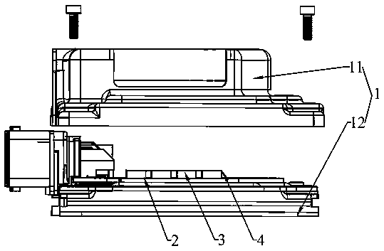
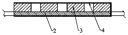
[0052] Such as Figure 1-4 As shown, the BMS heat dissipation structure of Embodiment 1 includes a housing 1 and a BMS protection plate 2 disposed in the housing. A MOS tube 3 is fixedly arranged on the outer edge of the BMS protection plate 2. The housing 1 includes an upper housing 11 and the lower case 12, the assembly of the BMS protection plate 2 and the MOS tube 3 and the upper case 11, and the assembly and the lower case 12 are closely fitted with a heat conduction sheet 4; The side ends are integrally connected.
[0053] In Embodiment 1, the MOS tubes 3 are all arranged above the BMS protection board.
[0054] The material of the housing 1 is aluminum. The upper housing 11 includes an open box-shaped central part 111 and a sealing edge 112 located on the outer periphery of the central part. The central part 111 is provided with a recessed part a, and the inner surface a1 of the recessed part is attached to the heat conducting sheet 4. ; The heat conduction sheet 4 is...
Embodiment 2
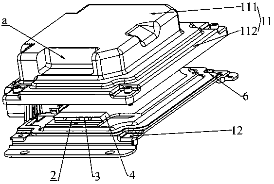
[0056] Such as Figure 5-8 Shown, embodiment 2 is based on embodiment 1, difference is:
[0057] The assembly is integrally connected with the same-side end of the heat conducting sheet 4 between the upper case 11 and the lower case 12 and combined into a closed loop.
[0058] The outer surface of the upper casing 11 is provided with heat dissipation fins 5 , and the heat dissipation fins 5 are arranged opposite to the joints of the heat conduction fins on the inner surface of the upper casing.
[0059] The adhesive-backed graphite sheet is directly bonded to the assembly of the BMS protection plate 2 and the MOS tube 3 .
[0060] A sealing ring 6 is arranged between the upper casing 11 and the lower casing 12; the top surface of the central part 111 of the upper casing 11 is opposite to the opening, and the inner concave surface of the recessed part a transitions from the top surface of the casing to the side of the central part 111 , the recessed part a is located between ...
Embodiment 3
[0063] Such as Figure 9 As shown, Embodiment 3 is based on Embodiment 2, and the MOS transistor 3 is separately arranged on the upper and lower sides of the BMS protection plate 2 .
PUM
 Abstract
Description
Claims
Application Information
 - R&D
- Intellectual Property
- Life Sciences
- Materials
- Tech Scout
- Unparalleled Data Quality
- Higher Quality Content
- 60% Fewer Hallucinations
Browse by: Latest US Patents, China's latest patents, Technical Efficacy Thesaurus, Application Domain, Technology Topic, Popular Technical Reports.
© 2025 PatSnap. All rights reserved.Legal|Privacy policy|Modern Slavery Act Transparency Statement|Sitemap|About US| Contact US: help@patsnap.com