Outer rotor brushless motor

A brushless motor and outer rotor technology, applied in electrical components, electromechanical devices, and connection with control/drive circuits, etc., can solve the problems of increased assembly difficulty, small thermal contact area, damaged insulation layer, etc., to improve reliability, High assembly precision and avoid open circuit effect

Pending Publication Date: 2020-02-21
JIANGSU LANGXIN ELECTRIC
View PDF1 Cites 0 Cited by
  • Summary
  • Abstract
  • Description
  • Claims
  • Application Information

AI Technical Summary

Problems solved by technology

Before that, the applicant applied for a driving motor for automobile cooling fan, and its patent application number is: CN201810896239.X. The specific structure of the driving motor can refer to the application document. The applicant found the above-mentioned driving motor when recreating There are still certain shortcomings, as follows: 1. The above-mentioned conductive bracket of the driving motor is placed in the conductive bracket installation area, and then the PCBA board is installed on the conductive bracket, and there is no other positioning structure between the conductive bracket and the heat sink. Therefore, there may be looseness. At the same time, if the conductive bracket is placed in the conductive area, it may be difficult to guarantee the matching accuracy between the heat sink and the conductive bracket due to the processing accuracy; 2. The above-mentioned inductor of the drive motor is installed in the inductor installation area. However, the current installation area of ​​this kind of inductor is a planar structure. The inductor is placed and fixed on the plane through thermal conductive glue, and the pins of the inductor are placed on the conductive bracket and welded and fixed with the PCBA board. When placed on a flat surface, the thickness of the heat-conducting adhesive may be uneven, the heat-conducting contact area between the heat-conducting adhesive and the cylindrical inductor is small, and the heat-conducting effect is poor. At the same time, the insulating layer of the inductor may be damaged during the use of the motor or the installation of the inductor. 3. The length of the current positioning slot is relatively long, and it takes a lot of force to embed the conductive connecting rod into the positioning slot, resulting in assembly The difficulty increases; 4. The heat dissipation effect of the heat sink of the current brushless motor is not good enough, and the heat conduction contact area between the PCBA board and the heat sink is relatively small, and the heat conduction efficiency is relatively low; 5. The current conductive connecting rod The tail end passes through the hole of the PCBA board and is welded and fixed. However, for the reliability of welding, a section of the tail end of the conductive connecting rod needs to be exposed. Once the rear end cover is deformed during use, the rear end cover may touch The tail end of the conductive connecting rod will also cause a short circuit; 6. The shape of the heat dissipation cover of the above-mentioned motor has some included angles, and the transition of the included angle is very rigid, which makes it difficult to make the mold; 7. The current heat dissipation The seat is equipped with a waterproof and breathable film for waterproof and breathable, but the current installation method of the waterproof and breathable film is to set a breathable installation hole on the cooling seat, the waterproof and breathable film is placed in the installation hole, and then through the sealing ring and the interference However, in the process of use, once there is a misoperation, push the waterproof and breathable membrane from the outside of the mounting hole or the retaining ring may become loose during the working process of the motor, and finally come out from the mounting hole, and the protruding retaining ring is in the The internal sloshing of the motor may easily cause an internal short circuit

Method used


Image

  • Outer rotor brushless motor
  • Outer rotor brushless motor
  • Outer rotor brushless motor

Examples


Embodiment Construction

[0027] The present invention will be described in further detail below through specific examples.

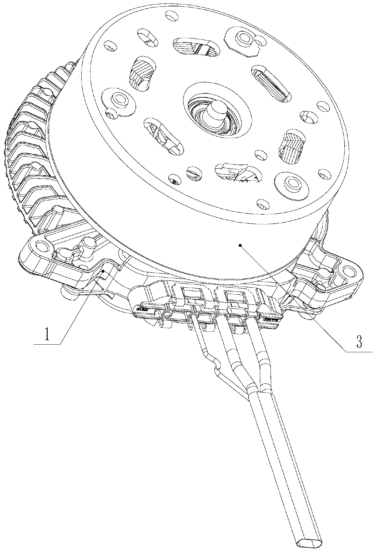
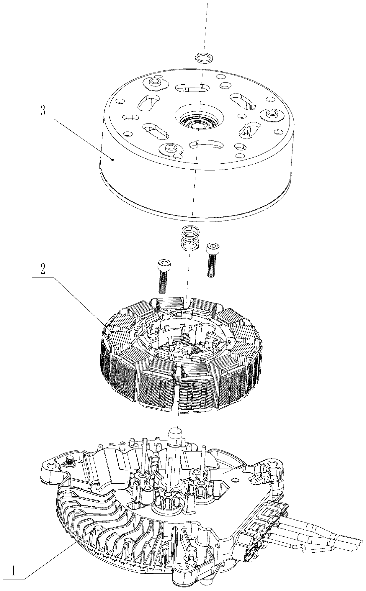
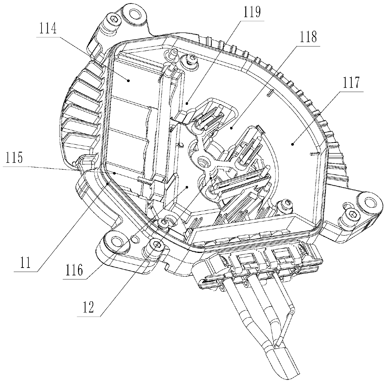
[0028] Such as Figure 1 to Figure 10 As shown, a brushless motor with an outer rotor includes a controller set, and the controller set includes a housing composed of a heat sink 11 and a rear end cover 13, and a conductive bracket 12 and a PCBA are arranged inside the housing plate, the front of the heat sink 11 is provided with a central shaft, the front of the heat sink 11 is equipped with an armature assembly 2, the central shaft is rotated and installed with an outer rotor assembly 3, and the heat sink 11 is provided with a capacitor installation area 114, inductance installation area 115, conductive support 12 installation area 1110, wire harness connector area and heat conduction platform, described conductive support 12 is placed in the conductive support 12 installation area 1110, and capacitor is installed in the capacitance installation area 114, in the inductance ins...


PUM


Abstract

The invention discloses an outer rotor brushless motor which comprises a controller assembly. The controller assembly comprises a casing composed of a heat dissipation base and a rear end cover. A conductive support and a PCBA board are arranged in the casing. A positioning structure is arranged between the back surface of the heat dissipation base and the conductive support. A waterproof breathable mounting hole is formed in the heat dissipation base. A waterproof breathable film, a sealing ring and a check ring are sequentially mounted in the waterproof breathable mounting hole from front toback. The check ring is in interference fit with the waterproof breathable mounting hole. The conductive support is provided with a limiting plate portion used for limiting the check ring from disengaging from the waterproof breathable mounting hole. The limiting plate portion covers the reverse side of the waterproof breathable mounting hole and is provided with a through hole, and the diameterof the through hole is smaller than the diameter of the check ring. The brushless motor not only can facilitate the positioning and installation of the conductive support and the heat dissipation base, but also can avoid the falling of the check ring to avoid a disconnection phenomenon. The service life of the brushless motor is prolonged. The reliability is improved.

Description

technical field [0001] The invention relates to a brushless motor, in particular to a motor for controlling a cooling fan of an automobile. Background technique [0002] Motors are commonly used power devices and are used in various industries. At present, brushless motors can be controlled by PCBA boards. Before that, the applicant applied for a driving motor for automobile cooling fan, and its patent application number is: CN201810896239.X. The specific structure of the driving motor can refer to the application document. The applicant found the above-mentioned driving motor when recreating There are still certain shortcomings, as follows: 1. The above-mentioned conductive bracket of the driving motor is placed in the conductive bracket installation area, and then the PCBA board is installed on the conductive bracket, and there is no other positioning structure between the conductive bracket and the heat sink. Therefore, there may be looseness. At the same time, if the co...

Claims


Application Information

Patent Timeline
Patent Type & Authority Applications(China)
IPC IPC(8): H02K11/30H02K29/00
CPCH02K11/30H02K29/00
Inventor 丁言闯徐迎宾陈志强
Owner JIANGSU LANGXIN ELECTRIC
Why Eureka
Try Eureka