
A device and process for solidifying industrial and construction solid waste into building materials

A solid waste and construction technology, applied in the field of building materials, can solve the problems of lack of screening, inability to separate waste, and reduced applicability

Active Publication Date: 2021-05-14
邱景新
View PDF8 Cites 0 Cited by
  • Summary
  • Abstract
  • Description
  • Claims
  • Application Information

AI Technical Summary

Problems solved by technology

[0004] Due to the lack of screening, the above patents cannot separate industrial and construction solid wastes that cannot be pulverized, which reduces the applicability

Method used


Image

  • A device and process for solidifying industrial and construction solid waste into building materials
  • A device and process for solidifying industrial and construction solid waste into building materials
  • A device and process for solidifying industrial and construction solid waste into building materials

Examples


Embodiment 1

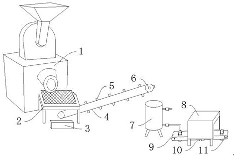
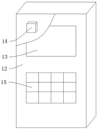
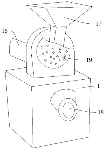
[0052] Such as Figure 1-Figure 9 As shown, a device for solidifying industrial and construction solid waste into building materials includes a pulverizer 1, a screening frame 2, and a shaping box 8. The pulverizer 1 includes a feeding hopper 17, and a pulverizing disc 19 is arranged behind the feeding hopper 17. A crushing motor 16 is arranged behind the crushing disc 19, a discharge port 18 is provided in front of the pulverizer 1, a screening frame 2 is arranged below the discharge port 18, a screening motor 22 is arranged above the screening frame 2, and a screening motor 22 is arranged below the screening motor 22. A support seat 35 is provided, an eccentric wheel 21 is arranged on the screening motor 22, a connecting shaft 23 is arranged on the eccentric wheel 21, a screening plate 20 is arranged on the connecting shaft 23, a collection box 3 is arranged in front of the screening frame 2, and the screening A first conveyor belt 4 is arranged below the sub-frame 2, a firs...

Embodiment 2

[0054] The difference between this embodiment and embodiment 1 is:

[0055] The crushing disc 19 is circular, and the crushing motor 16 and the crushing disc 19 are connected by splines, and the crushing motor 16 and the pulverizer 1 are connected by bolts. Smooth transmission, bolt connection is convenient for disassembly and maintenance of the crushing motor 16.

[0056] In this embodiment, the specific process method includes the following steps:

[0057] a. Put industrial and construction solid waste into the pulverizer 1 from the feed hopper 17, press the setting key 15 to set the parameters of each part, the controller 14 starts the pulverizing motor 16, and the pulverizing motor 16 drives the pulverizing disc 19 to pulverize the solid waste from Outlet 18 discharges.

[0058] b. Solid waste debris falls on the screening plate 20 from the discharge port 18, and the screening motor 22 rotates and drives the eccentric wheel 21 to drive the screening plate 20 to shake thr...


PUM


Abstract

The invention discloses a device for solidifying industrial and construction solid waste into building materials, which includes a pulverizer, a screening frame, and a shaping box. The pulverizer includes a feeding hopper, and a pulverizing disc is arranged behind the feeding hopper. A crushing motor is provided behind the crushing disc, a discharge port is provided in front of the pulverizer, the screening frame is provided below the discharge port, a screening motor is provided above the screening frame, and the screening motor A support base is arranged below, an eccentric wheel is arranged above the screening motor, and a connecting shaft is arranged above the eccentric wheel. The beneficial effect is that: the present invention utilizes the crushing plate to squeeze and grind the industrial and construction solid wastes, which ensures the crushing of the solid wastes, and at the same time uses the screening plate to classify the crushed solid wastes, and separates the solid wastes which cannot be crushed, avoiding The late blockage improves the applicability of the waste solidification into building materials device, and the use of automatic control of the water intake ensures the viscosity of the raw material mixing and facilitates the final setting.

Description

technical field [0001] The invention relates to the field of building materials. The invention relates to a device for solidifying industrial and construction solid waste into building materials and a process thereof. Background technique [0002] Construction waste is solid waste generated during the process of new building, renovation, expansion or demolition of buildings. According to the different sources of construction waste, it can be divided into construction waste and demolition construction waste. Construction waste, as the name implies, is the solid waste generated in new construction, renovation or expansion projects, and demolition construction waste is the construction waste generated during the demolition of buildings. Construction waste has a wide range of erosive effects on our living environment. If construction waste is ignored for a long time, it will have a bad impact on urban environmental sanitation, living conditions, and land quality assessment. ...

Claims


Application Information

Patent Timeline
Patent Type & Authority Patents(China)
IPC IPC(8): B09B3/00B09B5/00
CPCB09B5/00B09B3/80B09B3/20Y02W30/58
Inventor 邱景新
Owner 邱景新
Learn More