Homing type topological optimization method for mortise and tenon joint structure design

A connection structure and topology optimization technology, applied in design optimization/simulation, special data processing applications, geometric CAD, etc., can solve the problem that the boundary conditions of mortise and tenon structures cannot be applied drastically, and cannot give inspiring new structures. The direction and range of the form and shape change are limited, so as to improve the contact conditions and stress concentration, improve the global optimization ability, and improve the contact conditions and stress concentration.

Active Publication Date: 2020-02-25
GUANGXI AISHENG CHUANGZHI SCI & TECH CO LTD
View PDF9 Cites 2 Cited by
  • Summary
  • Abstract
  • Description
  • Claims
  • Application Information

AI Technical Summary

Problems solved by technology

This method requires preset shape variables, and the direction and range of shape changes are limited, so that the optimization process depends too much on the topology and shape of the initial structure, and it is impossible to give inspiring new structural forms
Therefore, this method can only be used to improve stress concentration, optimize contact conditions, etc., but cannot change the force transmission path of the structure
[0004] Although topology optimization technology can give new structural forms with enlightening significance, co

Method used


Image

  • Homing type topological optimization method for mortise and tenon joint structure design
  • Homing type topological optimization method for mortise and tenon joint structure design
  • Homing type topological optimization method for mortise and tenon joint structure design

Examples


Embodiment Construction

[0057] The following is attached Figure 1-11 The technical solutions involved in the present invention are described in detail.

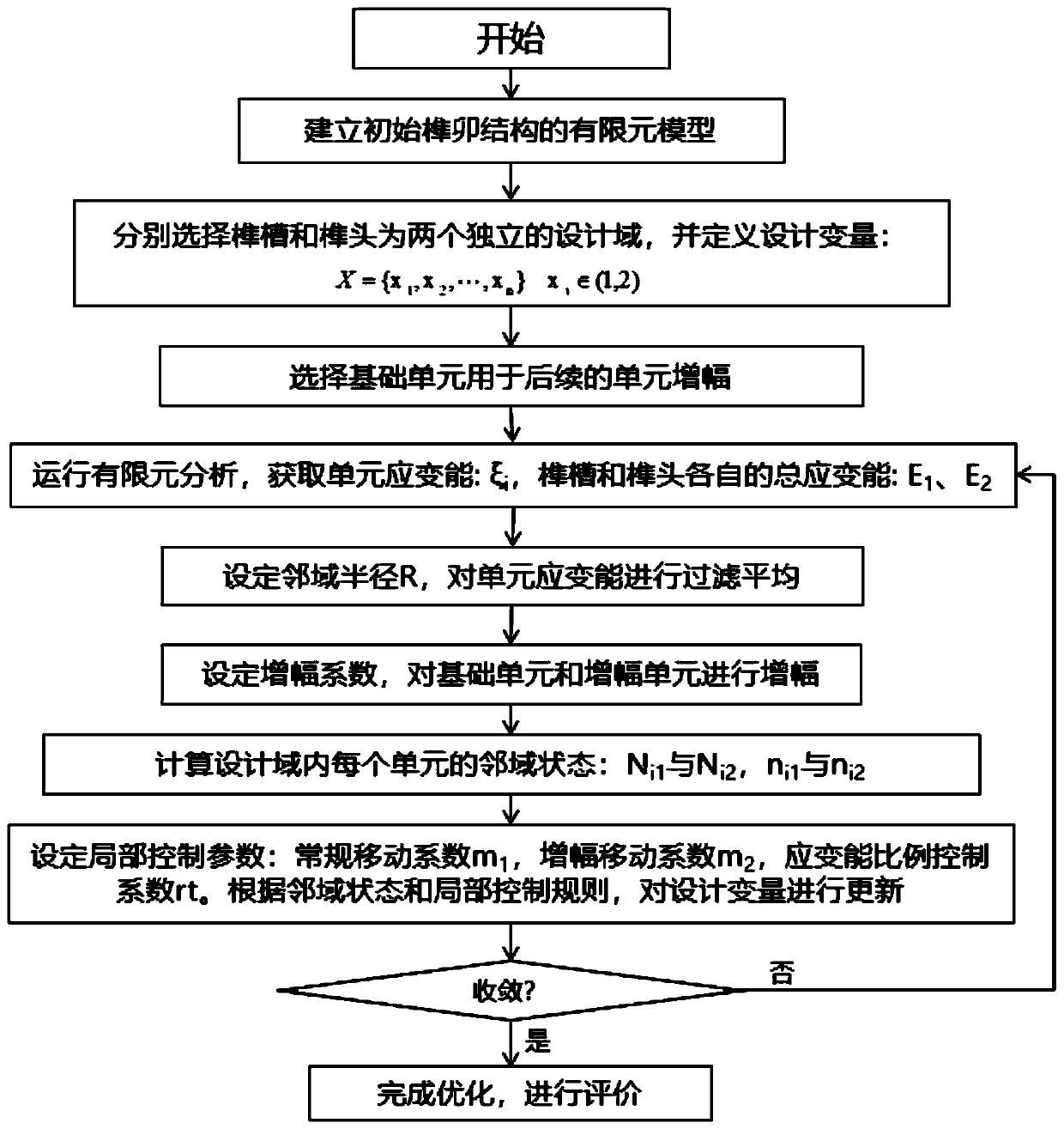
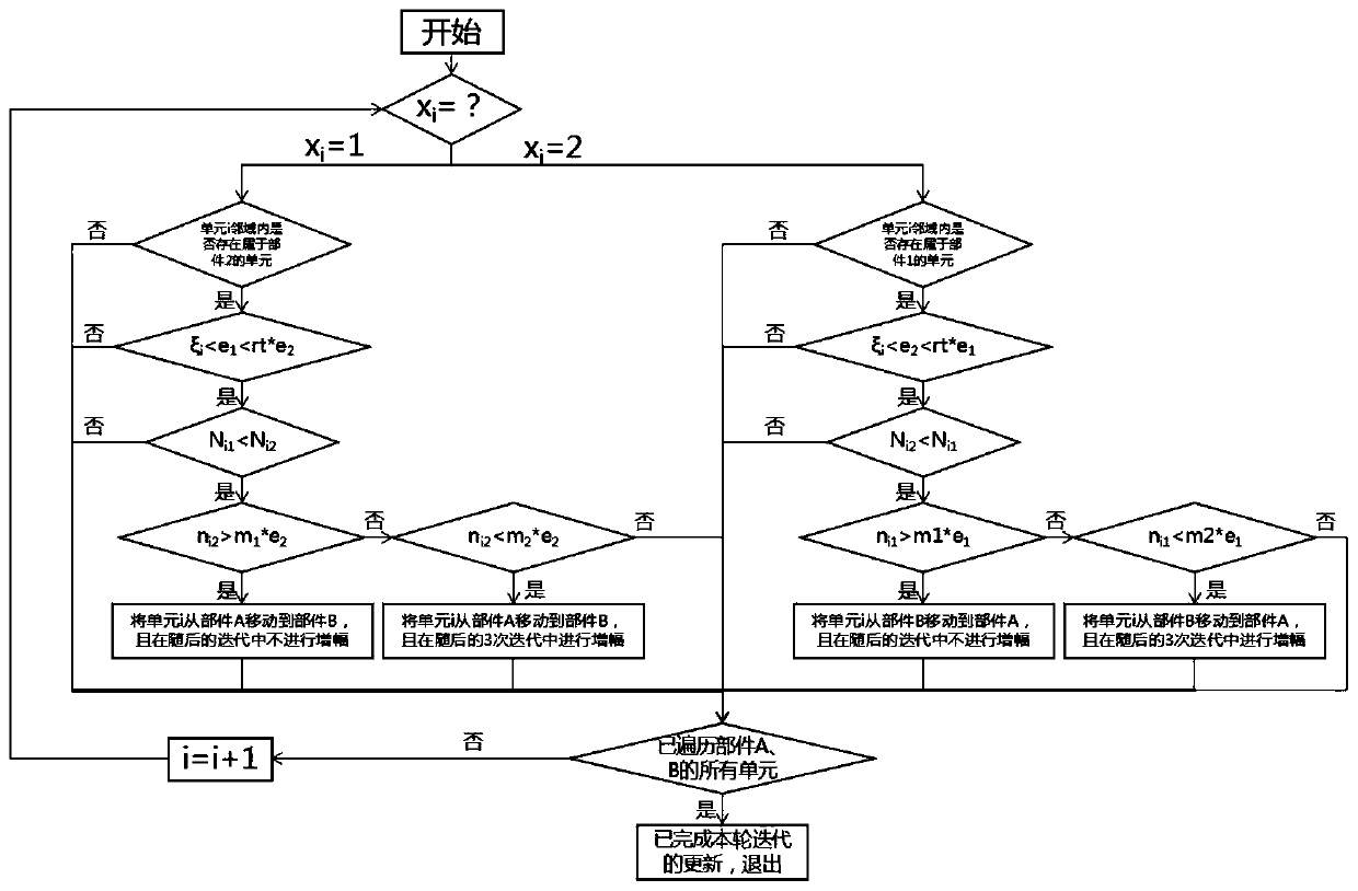
[0058] Such as figure 1 As shown, this embodiment provides a method for recursive topology optimization for the design of mortise and tenon joint structures, which specifically includes the following steps:

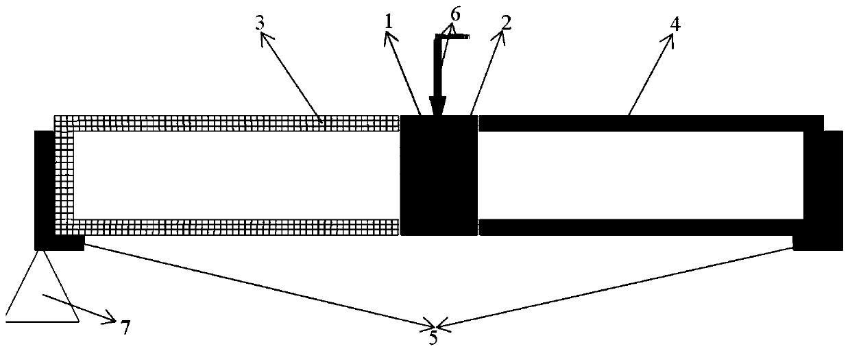
[0059] Step 1. Establish the finite element model of the structure to be optimized. The model includes: tenon groove 1, tenon head 2, left bearing structure 3, right bearing structure 4, support 5, downforce load 6 and constraint 7 on the support, The units of tenon and tenon 1 and tenon 2 are the design domain of the optimization problem. The selection of the design domain and the definition of the design variables will be detailed in step 2.

[0060] The established finite element model needs to ensure that the tenon 2 and the tenon groove 1 are completely fitted at the contact surface, and the grid nodes of the tenon 2 and the tenon groo...


PUM


Abstract

The invention discloses a homing type topological optimization method for mortise and tenon joint structure design. The homing type topological optimization method specifically comprises the followingsteps: step 1, establishing a finite element model of a to-be-optimized structure; step 2, selecting an area where a mortise (1) and a tenon (2) are located as a design domain; step 3, selecting a basic unit, and determining basic structural forms of the tenon (2) and the mortise (1); step 4, running primary finite element analysis; step 5, filtering and leveling the unit strain energy calculatedin the step 4; step 6, enabling the basic unit and the amplification unit to carry out amplification; step 7, calculating the neighborhood state of each unit in the design domain; step 8, setting local control parameters and constructing a local control rule; step 9, performing convergence judgment; and step 10, analyzing and evaluating an optimization result. According to the method, by changingthe basic shape form of the mutually matched and connected parts in the mortise and tenon joint structure, optimization can be conducted within a large range, and then the force transmission path ofthe mortise and tenon joint structure is optimized.

Description

technical field [0001] The invention relates to a topology optimization method, in particular to an optimal design method for assembled parts, butt joint parts, mortise and tenon structures or other structures that rely on the shape of the structure itself for mutual support, positioning and force transmission. Background technique [0002] With the development of engineering technology, thanks to the improvement of machining accuracy and the upgrading of assembly technology, combined and docking parts have been increasingly used in mechanical parts due to their high assembly efficiency and stable connection performance. In the design of joint parts, such as mortise and tenon structure, it is not limited to the application of traditional wooden structures, but has been adopted in a wider range of fields such as mechanical structure design and manufacture. In this context, the optimization of this fast connection structure has important practical significance. [0003] At pr...

Claims


Application Information

Patent Timeline
IPC IPC(8): G06F30/23G06F30/17
CPCG06F30/17G06F30/23
Inventor 宋凯程浦周晓斌
Owner GUANGXI AISHENG CHUANGZHI SCI & TECH CO LTD
Why Eureka
Try Eureka