
Automobile pillar B cross beam fixture

A crossbeam and B-pillar technology, which is applied to vehicle parts, manufacturing tools, auxiliary devices, etc., can solve the problems of lack of positioning of small parts, reduce processing accuracy, and occupy too much space, so as to improve positioning accuracy and processing accuracy, and improve Clamping stability, avoiding the effect of manual positioning

Pending Publication Date: 2020-02-28
LIUZHOU VOCATIONAL & TECHN COLLEGE +1
View PDF0 Cites 0 Cited by
  • Summary
  • Abstract
  • Description
  • Claims
  • Application Information

AI Technical Summary

Problems solved by technology

The traditional processing process requires a fixture to clamp the B-pillar beam of the car, and then weld the small parts such as the protrusion and the positioning block with the B-pillar of the car; the existing fixture has the following problems: lack of positioning for small parts, and welding of small parts by hand Will reduce the machining accuracy
If the traditional clamp is used to clamp small parts, a double-cylinder clamp is required. One cylinder controls the rise and fall of the bead to compress the beam, and the other cylinder is located next to the bead to control the positioning pin for positioning small parts. Due to the short distance between the first protrusion and the positioning block, two traditional clamps need to be installed to clamp the two first protrusions, and the cylinder controlling the positioning pin will occupy too much space and hinder the entry of the welding torch , it will inevitably affect the welding of the positioning block, and the welding operation cannot be performed

Method used


Image

  • Automobile pillar B cross beam fixture
  • Automobile pillar B cross beam fixture
  • Automobile pillar B cross beam fixture

Examples


Embodiment 1

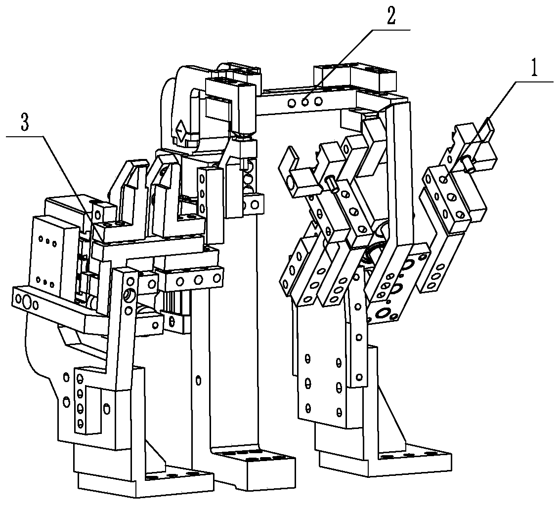
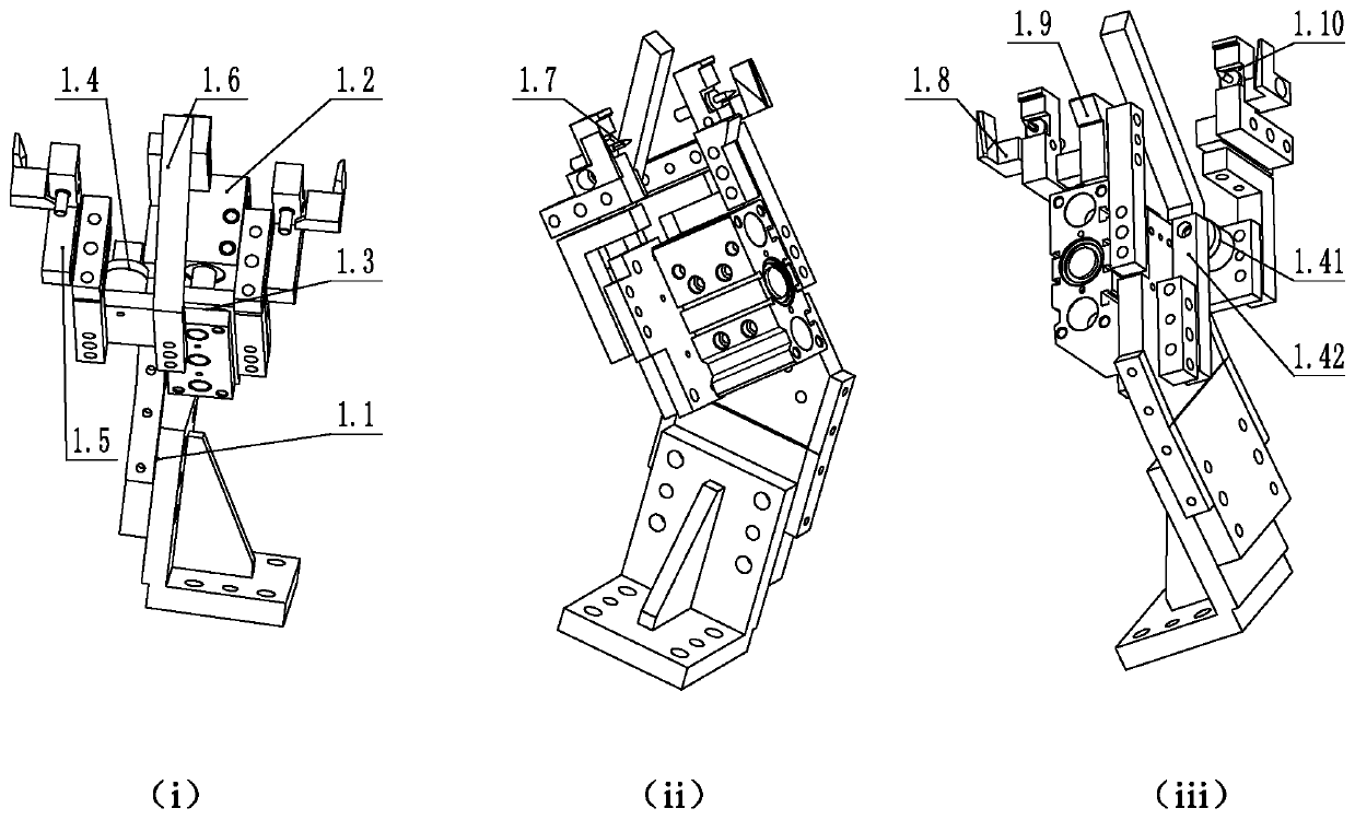
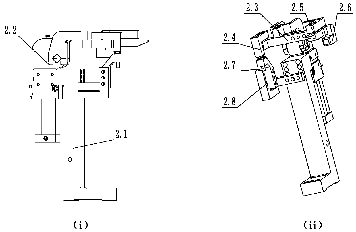
[0034] Such as Figure 1-4As shown, an automobile B-pillar crossbeam clamp includes a protrusion positioning unit 1, a clamping unit 2 and a positioning block positioning unit 3 arranged in sequence on the same substrate; the protrusion positioning unit 1 includes a first main installation Frame 1.1, the first main mounting frame 1.1 is provided with a first driving device 1.2, the first driving device 1.2 is a three-axis cylinder, the driving rod of the first driving device 1.2 expands and contracts obliquely downward, and the driving rod is fixedly connected to the first The moving plate 1.3 is provided with a contraction limiting device 1.4 within the contraction stroke of the first moving plate 1.3, and the contraction limiting device 1.4 is connected with the first main installation frame 1.1; the left and right ends of the first moving plate 1.3 are respectively provided with a set of protrusions Fixing devices, their structures are consistent and mirror-image symmetrica...


PUM


Abstract

The invention discloses an automobile pillar B cross beam fixture comprising a lug boss locating unit, a clamping unit and a locating block locating unit which are arranged in sequence; the lug boss locating unit comprises a first main mounting rack which is provided with a first driving device, and a driving rod of the first driving device extends downwards aslant, and fixedly connected with a first movable plate; a constriction limiting device is arranged within the backstroke of the first movable plate; the constriction limiting device is connected with the first main mounting rack; and theright and left ends of the first movable plate are each provided with a group of lug boss fixing devices separately, and the structures of the lug boss fixing devices are consistent in mirror symmetry. According to the automobile pillar B cross beam fixture, two lug bosses are controlled and located through one cylinder, and two locating blocks are controlled and located though one cylinder; then, through cooperation of clamping and pressing of the clamping unit, the vicinity of a welding point of each small component has an enough space for a welding gun to enter; and the problems that a single small component is located through a traditional double-cylinder fixture, a welding space is affected by the single small component and the traditional double-cylinder fixture, and consequently the welding gun can not enter the welding space are solved.

Description

technical field [0001] The invention belongs to the field of automobile workpiece fixtures, in particular to a B-pillar beam fixture of an automobile. Background technique [0002] Automobile B-pillar is the abbreviation of body pillar. Between the front and rear seats of the cockpit, the B-pillar is the longitudinal bar between the two doors on either side, extending from the roof to the bottom of the car. Such as Figure 5 As shown, the existing automobile B-pillar includes a crossbeam, and the crossbeam includes welded small part protrusions and positioning blocks. Two protruding parts, the distance between the first protruding part and the positioning block is relatively short, and there are many solder joints. It is necessary to firmly clamp the workpiece and maintain enough space to facilitate the entry of the welding torch. The traditional processing process requires a fixture to clamp the B-pillar beam of the car, and then weld the small parts such as the protrusio...

Claims


Application Information

Patent Timeline
Patent Type & Authority Applications(China)
IPC IPC(8): B23K37/04
CPCB23K37/0443B23K2101/006
Inventor 陈勇棠黄浩黄师张伶俐何泽显杨雲升雷健泳
Owner LIUZHOU VOCATIONAL & TECHN COLLEGE
Learn More