Air source heat pump single-layer or multi-layer centralized placement system
An air source heat pump, single-layer technology, applied in heat pumps, pump devices, pumps, etc., can solve the problems of cross-infection of air in and out, affecting air heat exchange efficiency, etc., to save floor space, large heat exchange temperature difference, and contain the impact Effect
- Summary
- Abstract
- Description
- Claims
- Application Information
AI Technical Summary
Problems solved by technology
Method used
Image
Examples
specific Embodiment approach 1
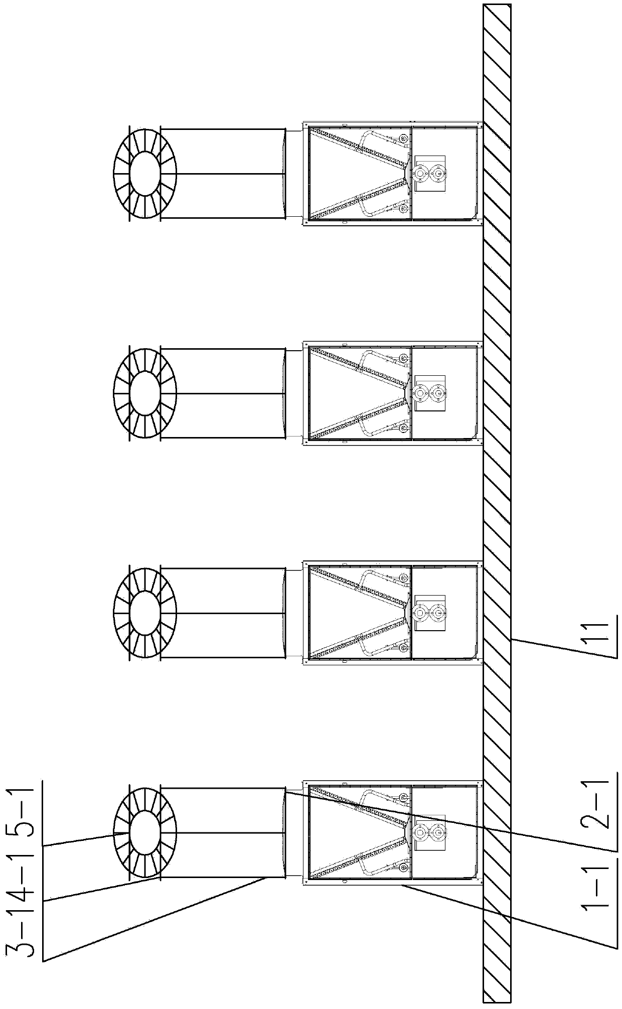
[0027] Specific implementation mode one, such as figure 1 As shown, a single-layer centralized placement system for air source heat pumps in this embodiment consists of an air source heat pump unit 1-1, an axial flow fan 2-1, a pipe section 3-1, and an air duct outlet 4 -1 and wind cap one 5-1, the air source heat pump unit one 1-1 is connected with the axial flow fan one 2-1, and the axial flow fan one 2-1 is connected with the pipe section one 3-1; the pipe section one The other end of the 3-1 is connected to the air outlet 4-1 of the air duct, and the air cap 5-1 is arranged on the upper part of the air outlet 4-1 of the air duct. Air source heat pump unit one 1-1, axial flow fan one 2-1, pipe section one 3-1, air duct outlet one 4-1 and air cap one 5-1 form the air duct device A1. Multiple air duct devices A1 are placed on a single-layer welded steel frame 11 . The beneficial effect of this embodiment is that air ducts are used to exhaust air independently, effectively p...
specific Embodiment approach 2
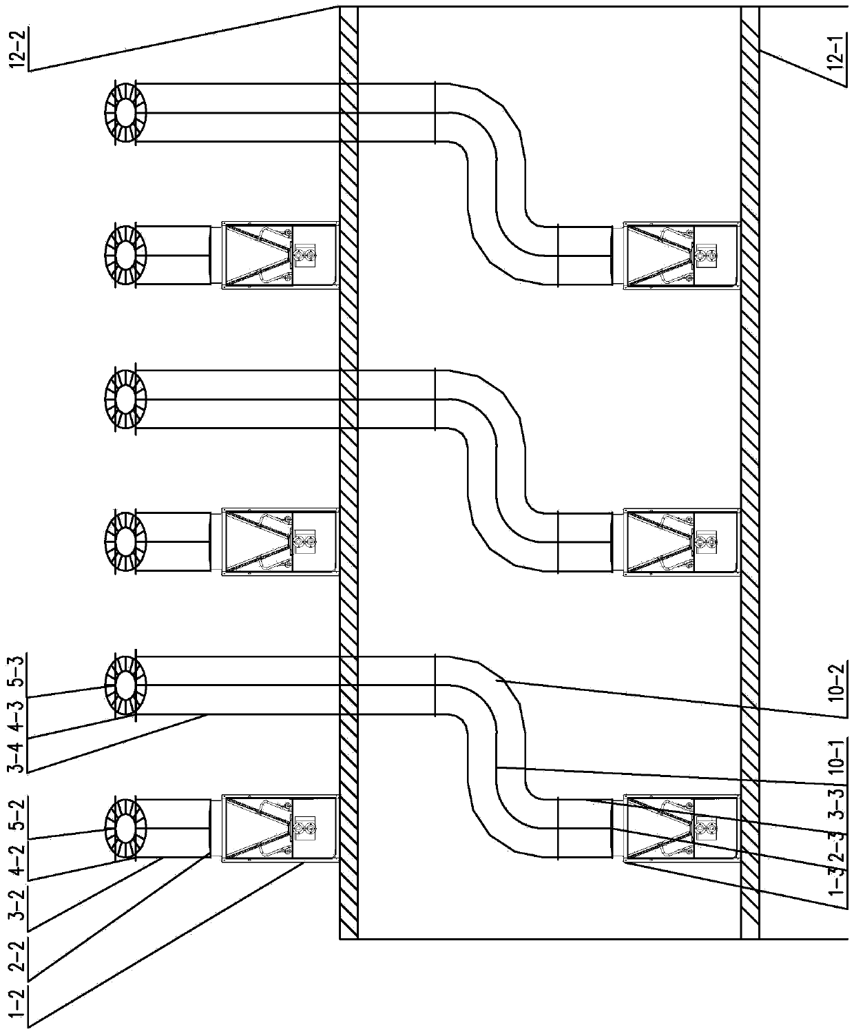
[0028] Specific implementation mode two, such as figure 2 As shown, a double-layer centralized placement system for air source heat pumps in this embodiment consists of air source heat pump unit two 1-2, air source heat pump unit three 1-3, axial flow fan two 2-2, axial flow fan Three 2-3, pipe section two 3-2, pipe section three 3-3, pipe section four 3-4, air duct elbow one 10-1, air duct elbow two 10-2, air duct outlet two 4-2, Air pipe outlet three 4-3, wind cap two 5-2 and wind cap three 5-3, the air source heat pump unit two 1-2 is connected with axial flow fan two 2-2, axial flow fan two 2- 2 is connected with the second pipe section 3-2; the other end of the second pipe section 3-2 is connected with the second air outlet 4-2 of the air duct, and the second air cap 5-2 is arranged on the upper part of the second air outlet 4-2 of the air duct. Air source heat pump unit 2 1-2, axial flow fan 2 2-2, pipe section 2 3-2, pipe section 2 3-2, air duct outlet 2 4-2, and air ...
specific Embodiment approach 3
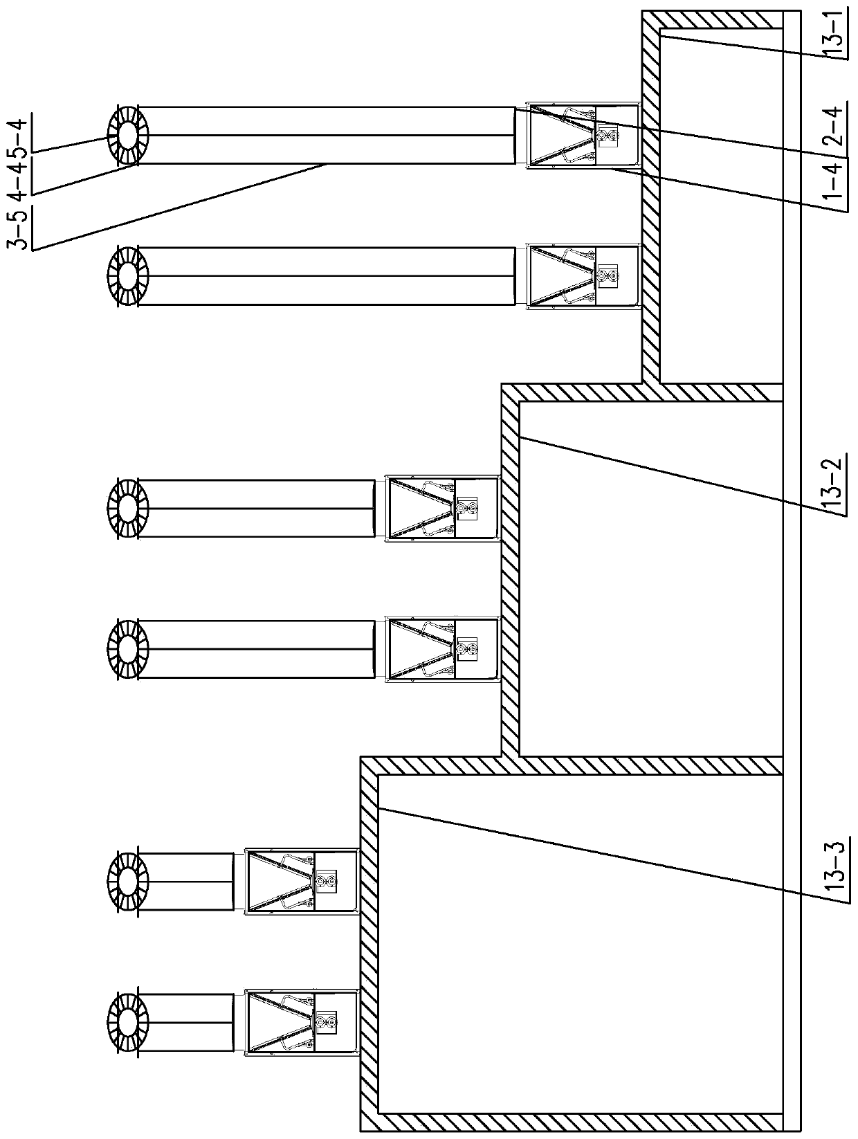
[0029] Specific implementation mode three, such as image 3 As shown, an air source heat pump multi-layer centralized placement system in this embodiment is composed of air source heat pump unit 4 1-4, axial flow fan 4 2-4, pipe section 5 3-5, air duct outlet 4 4- 4 and wind cap 4 5-4, the air source heat pump unit 4 1-4 is connected with axial flow fan 4 2-4, axial flow fan 4 2-4 is connected with pipe section 5 3-5; pipe section 5 3 The other end of -5 is connected to the air outlet 4-4 of the air duct, and the air cap 4 5-4 is set on the upper part of the air outlet 4-4 of the air duct; the air source heat pump unit 4 1-4, and the axial flow fan 4 2-4 , pipe section five 3-5, air duct air outlet four 4-4 and wind cap four 5-4 form the air duct device A3. The air duct device B2 and the air duct device C are connected in the same way as the air duct device A3; the air duct device A3 is placed on the multi-layer welded steel frame 13-1, and the air duct device B2 is placed on t...
PUM
 Abstract
Description
Claims
Application Information
 - R&D Engineer
- R&D Manager
- IP Professional
- Industry Leading Data Capabilities
- Powerful AI technology
- Patent DNA Extraction
Browse by: Latest US Patents, China's latest patents, Technical Efficacy Thesaurus, Application Domain, Technology Topic, Popular Technical Reports.
© 2024 PatSnap. All rights reserved.Legal|Privacy policy|Modern Slavery Act Transparency Statement|Sitemap|About US| Contact US: help@patsnap.com


