Decoupling Fabry-Perot resonant cavity

A resonant cavity and reflector technology, applied in the field of FP resonator, can solve the problem of little effect on gain, and achieve the effect of increasing antenna gain, improving phase distribution, and reducing mutual coupling

Inactive Publication Date: 2020-02-28
NANJING UNIV OF POSTS & TELECOMM
View PDF5 Cites 7 Cited by
  • Summary
  • Abstract
  • Description
  • Claims
  • Application Information

AI Technical Summary

Problems solved by technology

However, the above methods only focus on reducing mut

Method used


Image

  • Decoupling Fabry-Perot resonant cavity
  • Decoupling Fabry-Perot resonant cavity
  • Decoupling Fabry-Perot resonant cavity

Examples


Embodiment Construction

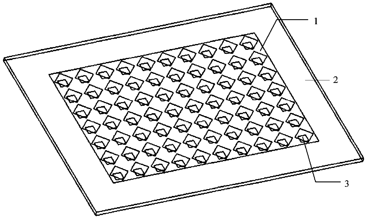
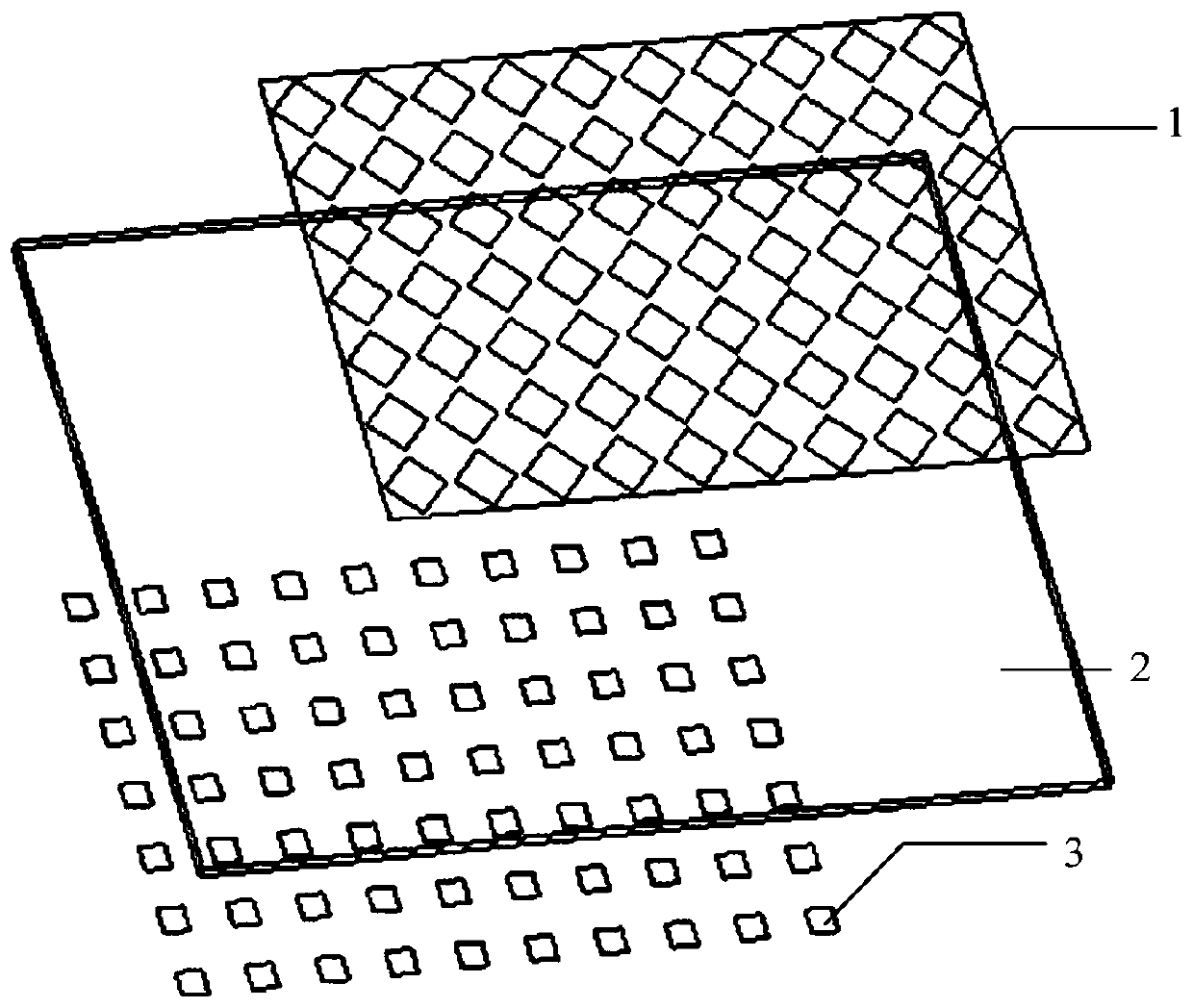
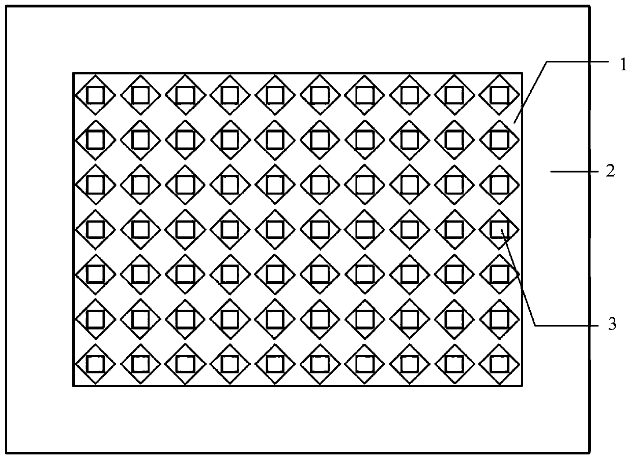
[0030] decouple the FP resonator, including upper layers such as Figure 1-3 The partially reflective surface shown, and the underlying layer as Figure 4-6 For the reflectarray and 1x2 patch antenna array shown, the distance between the upper and lower layers is 3.2mm. The partially reflective surface includes an upper metal layer 1 , a lower metal layer 3 and a dielectric substrate 2 . Among them, the upper metal layer 1 is composed of 7x10 square metal units with a period of 8mm, and each unit has a diamond-shaped groove with a side length of 5mm; the lower metal layer 3 is also composed of 7x10 square units with a period of 8mm, each unit The center is a square patch with a side length of 6mm. The thickness of the dielectric substrate 2 is 1.524mm, and the overall size is 80x104mm 2 , choose Taconic TLY-5 with relative permittivity 2.2 and loss tangent 0.0009.

[0031] The reflect array and the 1x2 patch antenna array include the upper metal layer 4 of the reflect arra...


PUM


Abstract

The invention discloses a decoupling Fabry-Perot (FP) resonant cavity, which comprises a partial reflection surface and a reflective array, and is characterized in that a coaxial feed 1*2 patch antenna array is embedded into the reflection array for observing coupling characteristics. The partial reflection surface is composed of 7*10 units, wherein each unit is composed of an upper metal layer, adielectric substrate and a lower metal layer, the upper metal layer is provided with a rhombic groove, and the lower metal layer is a square patch. The reflective array is composed of an upper metallayer, a dielectric substrate and a lower metal ground plate. The 1*2 patch antenna array consists of two square patches with the same size and a feed probe, and is embedded into the reflective array.Through the FP resonant cavity, the antenna gain can be effectively improved while the coupling between the antennas is reduced, and meanwhile, the antenna profile is also reduced.

Description

technical field [0001] The invention relates to an FP resonant cavity, in particular to a decoupling Fabry-Perot (FP) resonant cavity, which belongs to the field of microwave technology. Background technique [0002] As the basis of multiple-input multiple-output (MIMO) technology, antenna arrays are widely used in modern mobile communication and phased array radar communication systems. As an important indicator of the antenna array, mutual coupling will seriously deteriorate its radiation performance. [0003] In the antenna array, the mutual coupling mainly comes from the surface wave of the medium interface and the space electromagnetic field. Based on the above two points, people have done a lot of work on reducing the mutual coupling between antennas: planting electromagnetic bandgap structures between adjacent antennas to Suppress surface wave propagation; etch defective structures on the metal floor to disturb the induced current; place separate resonant rings betwe...

Claims


Application Information

Patent Timeline
IPC IPC(8): H01Q1/52H01Q1/38H01Q1/50H01Q15/14H01Q19/10H01Q21/00
CPCH01Q1/38H01Q1/50H01Q1/523H01Q15/145H01Q19/104H01Q21/0006
Inventor 战俊麟许锋
Owner NANJING UNIV OF POSTS & TELECOMM
Why Eureka
Try Eureka