Dyeing machine for food processing

A food processing and dyeing machine technology, applied in food forming, food science, application, etc., can solve the problems of small dyeing area and inability to adapt well, and achieve the effect provided by the dyeing effect

Inactive Publication Date: 2020-03-03
段婷
0 Cites 0 Cited by

AI-Extracted Technical Summary

Problems solved by technology

[0003] Existing foods more or less use food colorants during processing, but when coloring foods, most of them use...

Method used

A kind of food processing dyeing machine comprises dyeing container 1, and described dyeing container 1 bottom is connected with conveying pipe 2, and described conveying pipe 2 is connected with dyeing fixed frame 3, and one end of described dyeing fixed frame 3 is provided with dyeing measuring cylinder 4. A push plate 5 is arranged in the dyeing measuring cylinder 4, a draw-in groove is arranged in the push plate 5, a partition 6 is arranged in the draw-in groove, and a guide rod 7 is arranged on the top of the divider 6. The tail of the dyeing measuring cylinder 4 is provided with a dyeing needle 8 . This application can carry out needle tube type injection dyeing for the dyeing needs of small areas, and in the process of dyeing, it can be driven by the horizontal cylinder 12 to make the push plate 5 in the dyeing measuring cylinder 4 do horizontal reciprocating actions to realiz...

Abstract

The invention belongs to the field of food processing equipment, and especially relates to a dyeing machine for food processing. The dyeing machine includes a dyeing container, the bottom of which isconnected with a conveying pipe. The conveying pipe is connected with a dyeing fixed mount, one end of which is provided with a dyeing measuring cylinder. A push plate is arranged in the dyeing measuring cylinder. A neck is arranged in the push plate, and a partition plate is arranged in the neck. A guide rod is arranged at the top of the partition plate, and a dyeing needle is arranged at the tail of the dyeing measuring cylinder. The needle-type injected dyeing can be performed according to the dyeing requirement of a small area, and during the dyeing process, through the drive of the horizontal cylinder, the push plate in the dyeing measuring cylinder can perform horizontal reciprocating action to push a colorant, and the neck can be driven by a lifting cylinder to move up and down to realize the injection of the colorant. As the guide rod is arranged, the push plate can be driven by the cylinder to move, and the dyeing effect is greatly enhanced.

Application Domain

Food shaping

Technology Topic

DyeingEngineering +4

Image

  • Dyeing machine for food processing

Examples

  • Experimental program(2)

Example Embodiment

[0015] Example 1
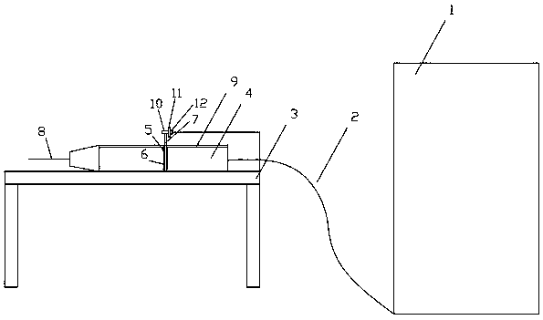
[0016] A food processing dyeing machine includes a dyeing container 1, a conveying tube 2 is connected to the bottom of the dyeing container 1, the conveying tube 2 is connected to a dyeing fixing frame 3, and one end of the dyeing fixing frame 3 is provided with a dyeing cylinder 4, so The dyeing cylinder 4 is provided with a push plate 5, a card slot is provided in the push plate 5, a partition plate 6 is provided in the card groove, a guide rod 7 is provided on the top of the partition plate 6, and the dyeing cylinder 4 A dyeing needle 8 is provided at the tail of the This application can perform needle-tube injection dyeing for dyeing needs of a small area, and in the dyeing process, it can be driven by the horizontal cylinder 12 to make the push plate 5 in the dyeing cylinder 4 perform a horizontal reciprocating action to achieve the The coloring agent is pressed and the slot is moved up and down under the driving of the lifting cylinder 10 to realize the injection of the coloring agent. Due to the guide rod 7 provided, the push plate 5 can be driven by the cylinder to move, and the dyeing effect is greatly improved.

Example Embodiment

[0017] Example 2
[0018] A food processing dyeing machine includes a dyeing container 1, a conveying tube 2 is connected to the bottom of the dyeing container 1, the conveying tube 2 is connected to a dyeing fixing frame 3, and one end of the dyeing fixing frame 3 is provided with a dyeing cylinder 4, so The dyeing cylinder 4 is provided with a push plate 5, a card slot is provided in the push plate 5, a partition plate 6 is provided in the card groove, a guide rod 7 is provided on the top of the partition plate 6, and the dyeing cylinder 4 A dyeing needle 8 is provided at the tail of the
[0019] The dyeing cylinder 4 is provided with a guide groove 9, and the guide rod 7 passes through the guide groove 9.
[0020] A lifting cylinder 10 is connected to the guide rod 7.
[0021] A fixed plate 11 is connected to the lifting cylinder 10, and a horizontal cylinder 12 is connected to the fixed plate 11.
[0022] This application can perform needle-tube injection dyeing for dyeing needs of a small area, and in the dyeing process, it can be driven by the horizontal cylinder 12 to make the push plate 5 in the dyeing cylinder 4 perform a horizontal reciprocating action to achieve the The coloring agent is pressed and the slot is moved up and down under the driving of the lifting cylinder 10 to realize the injection of the coloring agent. Due to the guide rod 7 provided, the push plate 5 can be driven by the cylinder to move, and the dyeing effect is greatly improved.

PUM

no PUM

Description & Claims & Application Information

We can also present the details of the Description, Claims and Application information to help users get a comprehensive understanding of the technical details of the patent, such as background art, summary of invention, brief description of drawings, description of embodiments, and other original content. On the other hand, users can also determine the specific scope of protection of the technology through the list of claims; as well as understand the changes in the life cycle of the technology with the presentation of the patent timeline. Login to view more.
Why Eureka
Try Eureka