Nitrogen and oxygen sensor assembling, clamping and forming mold

A technology of nitrogen and oxygen sensors and forming molds, which is applied in the direction of manufacturing tools, auxiliary devices, vehicle parts, etc., and can solve problems such as high welding defective rate, unreasonable overall design of the bottom bracket and bucket seat, and deformation of the end of the nut jacket.

Inactive Publication Date: 2020-03-06
苏州忻智铭传感电子科技有限公司
View PDF0 Cites 0 Cited by
  • Summary
  • Abstract
  • Description
  • Claims
  • Application Information

AI Technical Summary

Problems solved by technology

At present, the common clamping molds have the following problems in the actual use process: 1. The overall design of the bottom bracket bucket seat is unreasonable, and the nut cover cannot be tightly tightened. The supporting components in the middle of the bottom bracket bucket seat cannot be adjusted according to different models The size of the nut jacket on the oxygen sensor is adjusted, and the adaptability is poor; 2. During the actual clamping production, the end of the nut jacket is prone to deformation, resulting in unqualified dimensions when the nitrogen and oxygen sensor chip components are subsequently installed; 3. During clamping The cylinder of the equipment pushes the clamping pneumatic push rod to move downward. When clamping the protective cover and the nut cover, the nut cover often moves out of position, so that the protective cover and the nut cover cannot be clamped and connected, resulting in defective welding products high rate

Method used


Image

  • Nitrogen and oxygen sensor assembling, clamping and forming mold
  • Nitrogen and oxygen sensor assembling, clamping and forming mold
  • Nitrogen and oxygen sensor assembling, clamping and forming mold

Examples


Embodiment Construction

[0016] The following will clearly and completely describe the technical solutions in the embodiments of the present invention with reference to the accompanying drawings in the embodiments of the present invention. Obviously, the described embodiments are only some, not all, embodiments of the present invention. Based on the embodiments of the present invention, all other embodiments obtained by persons of ordinary skill in the art without making creative efforts belong to the protection scope of the invention.

[0017] The present invention will be described in further detail below in conjunction with examples and specific implementation methods.

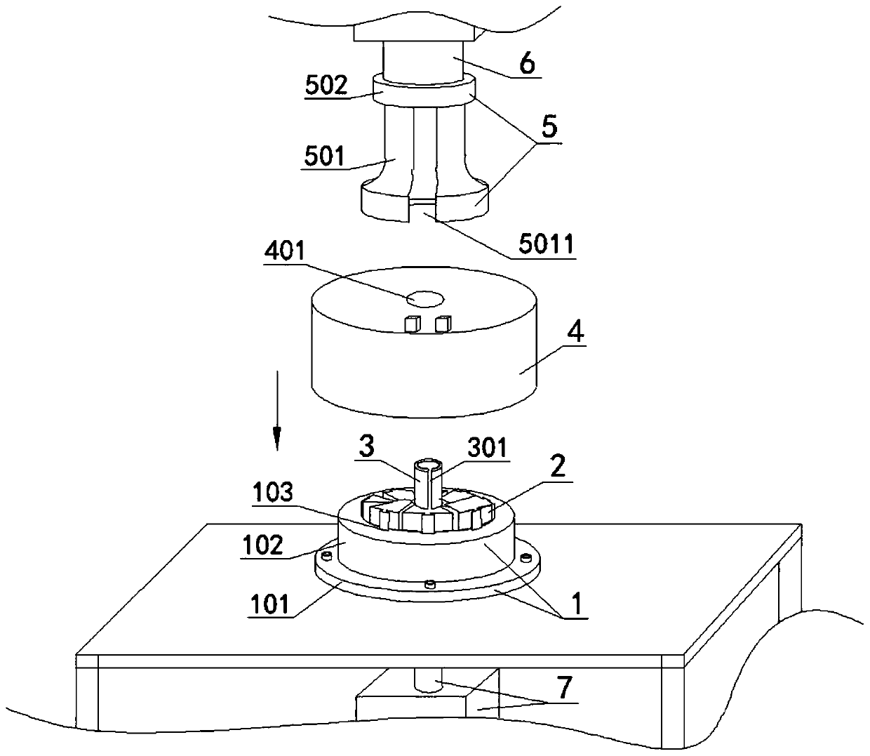
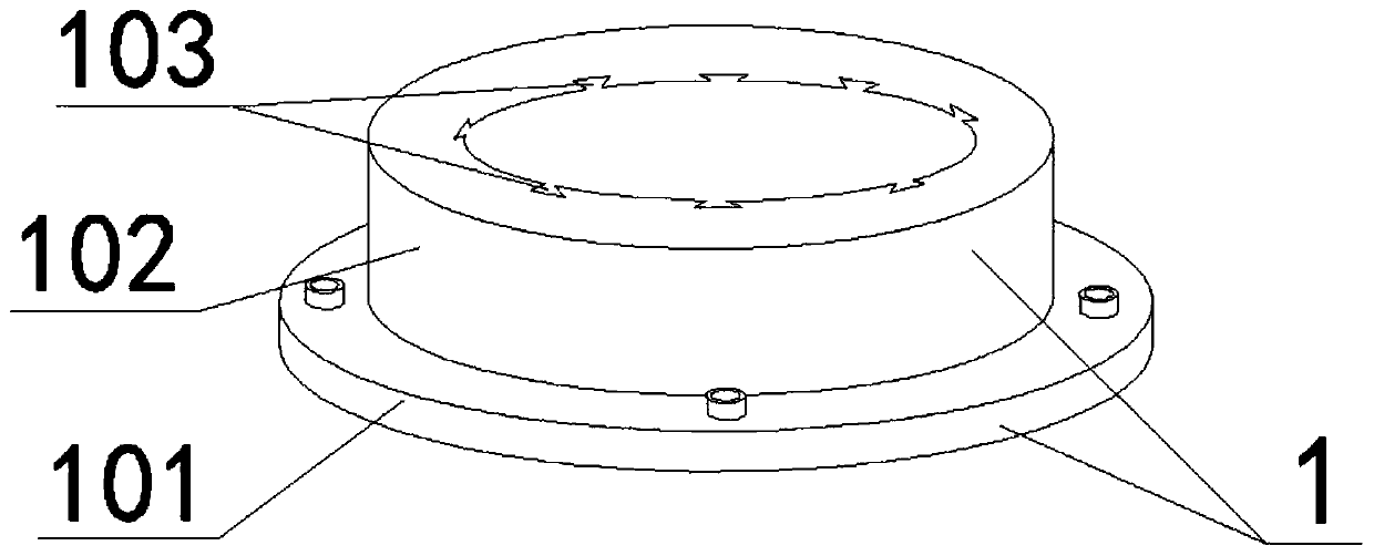
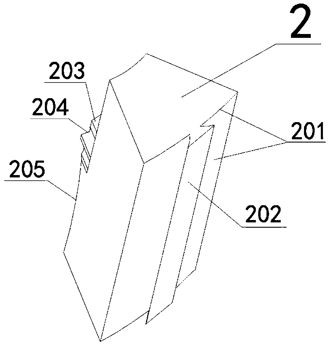
[0018] See the accompanying drawings: a nitrogen and oxygen sensor combined clamping forming mold, which is characterized in that it includes a bottom bracket bucket seat 1, a split clamping block mold 2, a positioning sleeve 4, a small limit cylinder 3 and an upper clamping mold 5, The bottom bracket bucket seat 1 is fixed and ins...


PUM


Abstract

The invention discloses a nitrogen and oxygen sensor assembling, clamping and forming mold. The nitrogen and oxygen sensor assembling, clamping and forming mold is characterized by comprising a bottomsupport barrel base, split clamping position block molds, a positioning sleeve and an upper clamping mold, the bottom support barrel base is fixedly installed in the middle of a working tabletop of aclamping device through bolts, the split clamping position block molds are installed on the upper face of the bottom support barrel base, the positioning sleeve overall sleeves the periphery of the outer side of the split clamping position block molds, the inner side of the bottom of the positioning sleeve is connected with the outer side of the bottom of the bottom support barrel base, and the upper clamping mold is fixedly installed on the lower side of a lower clamping pneumatic push rod of the clamping device. It can be ensured that the bottom of a front end protective sleeve head of a nitrogen and oxygen sensor is clamped by the front end of a nut sleeve according to different types of nitrogen and oxygen sensor nut sleeves, the nut sleeve can be clamped and limited on the upper faceof the split clamping position block molds, production efficiency is high, the deformation of the tail end of the nut sleeve of the nitrogen and oxygen sensor is avoided, clamping is firm, and no other matched assemblies of the nitrogen and oxygen sensor are damaged.

Description

technical field [0001] The invention relates to the field of an oxygen sensor combined clamping forming mold, in particular to a nitrogen oxygen sensor combined clamping forming mold. Background technique [0002] The nitrogen oxygen sensor is an important component of the fuel feedback control system of the automobile engine. During the manufacturing process of the nitrogen oxygen sensor, the protective sleeve at the front end of the nitrogen oxygen sensor needs to be clamped with the front end of the nut jacket. At this time, a clamping device is needed, and then The assembly after clamping the protective sleeve head and the front end of the nut sleeve is welded together by the welding equipment. When using the clamping equipment for processing, it is necessary to use the matching clamping forming mold. The clamping forming mold usually has a bottom bracket and an upper clamping mold. The bottom bracket is fixedly installed in the middle of the working table of the clampin...

Claims


Application Information

Patent Timeline
IPC IPC(8): B23K37/04
CPCB23K37/04B23K2101/006
Inventor 胡勤孟超王守明
Owner 苏州忻智铭传感电子科技有限公司
Why Eureka
Try Eureka