Accelerated pouring device for housing construction
A diverting device and conical technology, which is applied to the field of accelerated pouring and pouring devices for housing construction, can solve the problems of narrow pouring range and low speed, and achieve the effect of improving pouring efficiency and increasing pouring speed.
- Summary
- Abstract
- Description
- Claims
- Application Information
AI Technical Summary
Problems solved by technology
Method used
Image
Examples
Embodiment 1
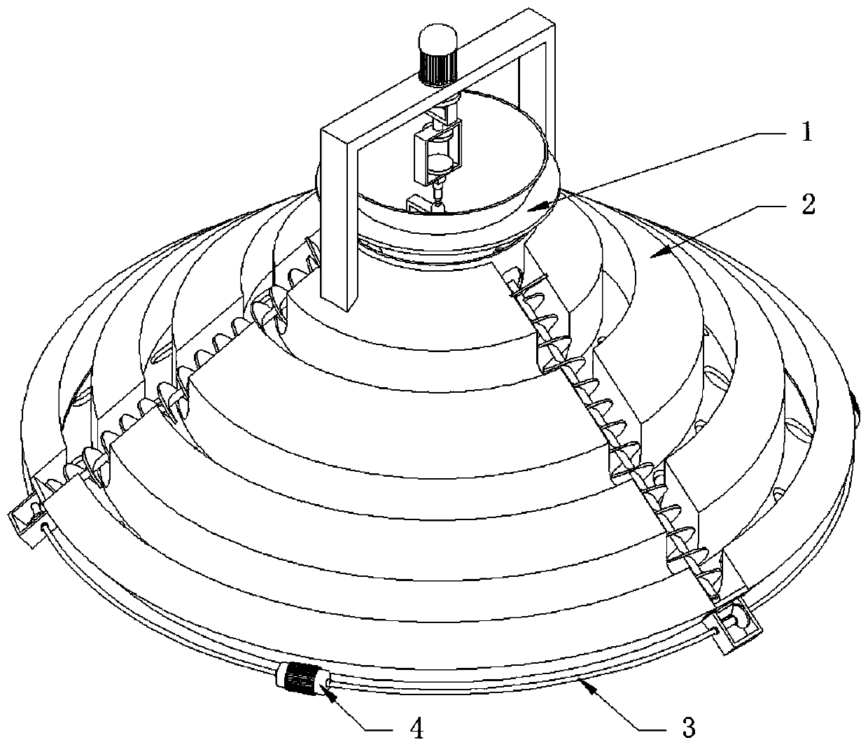
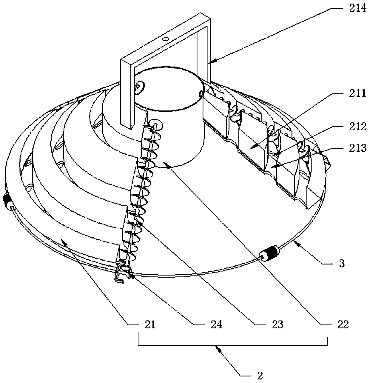
[0036] see Figure 1-6, an accelerated pouring device for house construction, comprising a dynamic lifting device 1 and a flow diversion device 2, the dynamic lifting device 1 is arranged on the upper part of the flow diversion device 2, and the flow distribution device 2 includes a conical diversion plate 21, located on the conical diversion plate 21 The barrel 22 in the middle and the conveying auger 23, the conical diverter plate 21 can be made into an umbrella shape, and the bottom can be connected to the legs to play a supporting role. The conical diverter plate 21 is provided with a diverter channel 211 and a discharge hole 212 And the diversion channel 213 that communicates with the distribution channel 211 and the blanking hole 212, the distribution channel 211 is radially distributed, the number of the distribution channel 211 is at least three and is uniformly distributed in the circumferential direction, the distribution channel 211 is a concave structure, and its ce...
Embodiment 2
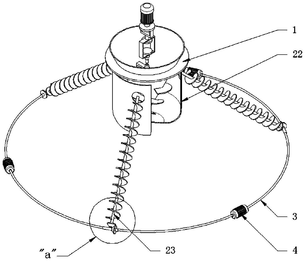
[0038] see Figure 2-3 The difference from Embodiment 1 is that the diverter device 2 also includes a bevel gear combination 24 that is rotatably connected to the outer periphery of the conical diverter plate 21, and the auger shaft of the conveying auger 23 is fixedly connected with the bevel gear combination 24, which is further described as , the bevel gear combination 24 includes a rotating shaft 241 distributed tangentially in the horizontal direction relative to the outer periphery of the conical diverter plate 21, a gear one 242 sleeved on the rotating shaft 241, and a gear two 243 sleeved on the auger shaft, a plurality of rotating shafts 241 is also connected with a drive motor 4 in series through the transmission flexible shaft 3, so that the drive motor 4 can drive a plurality of conveying augers 23 to rotate synchronously through the transmission flexible shaft 3, so as to realize the uniform distribution and blanking of the conical splitter plate 21, and also The ...
Embodiment 3
[0040] see Figure 5 The difference from Embodiment 1 is that the magnetic levitation device 15 includes a rectangular frame 151 fixedly connected to the bottom of the suspension frame 14, a bearing column 152 that slides up and down through the bottom of the rectangular frame 151, and a magnetic levitation device 153. The magnetic levitation device 153 includes a rectangular frame 151 The permanent magnet part 1531 fixedly connected to the inner top and the electromagnetic part 1532 fixedly connected to the top of the carrying column 152 utilize the principle of "magnetic levitation" to float up and down the carrying column 152" relative to the rectangular frame 151, which can be adjusted by changing the current in the electromagnetic part 1532. Changing the position of the bearing column 152, the bottom of the bearing column 152 and the top cross spherical hinge of the positioning frame 131 can then control the height of the conical conveying cylinder 11 in the material cylin...
PUM
 Abstract
Description
Claims
Application Information
 - R&D Engineer
- R&D Manager
- IP Professional
- Industry Leading Data Capabilities
- Powerful AI technology
- Patent DNA Extraction
Browse by: Latest US Patents, China's latest patents, Technical Efficacy Thesaurus, Application Domain, Technology Topic, Popular Technical Reports.
© 2024 PatSnap. All rights reserved.Legal|Privacy policy|Modern Slavery Act Transparency Statement|Sitemap|About US| Contact US: help@patsnap.com


