An accelerated pouring device for house construction
A diversion device and conical technology, which is applied in the field of accelerated pouring devices for housing construction, can solve problems such as low speed and narrow pouring range, and achieve the effect of increasing pouring speed and improving pouring efficiency
- Summary
- Abstract
- Description
- Claims
- Application Information
AI Technical Summary
Problems solved by technology
Method used
Image
Examples
Embodiment 1
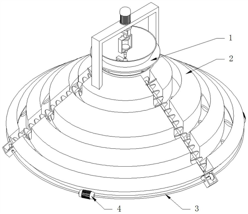
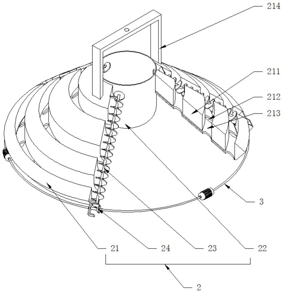
[0036] See Figure 1-6One room construction is accelerated, including the dynamic lifting device 1 and the shunt device 2, and the dynamic lift device 1 is disposed on the upper portion of the shunt device 2, and the shunt device 2 includes a tapered distribution disk 21, located in a cone-shaped distribution plate 21. The medium cartridge 22 and the conveying strap 23, the cone-shaped disk 21 can be used as an umbrella shape, and the bottom can be connected to support, and the cone-shaped disk 21 is provided with a shunt passage 211, the falling hole 212, and Connecting through the split channel 211 and the guide flow path 213 of the falling hole 212, the shunt passage 211 is radially distributed, and the number of shunt passages 211 is at least three and is uniformly distributed in a circumferential direction, and the shunt passage 211 is a recessed structure, which is penetrated to the heart The connecting barrel 22, the bottom portion of the cartridge 22 is lower than the direc...
Embodiment 2
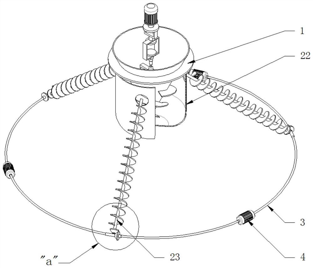
[0038] See Figure 2-3 The difference from the first embodiment is that the shunt device 2 further includes a cone gear combination 24, which is connected to the outer periphery of the cone-shaped disc 21, and the conveying connection of the twirling shaft and the cone gear combination 24 fixed to the twinkling 23, further depict The cone gear combination 24 includes a rotating shaft 241 tangential to the outer peripheral direction of the tapered bonding plate 21, a gear 242, a gear 242, a gear 243, a gear, a gear, a plurality of rotating shafts 241 There is also a driving motor 4 in series by the transmission soft shaft 3, whereby the drive motor 4 can drive a plurality of conveyed mover 23 by the transmission soft shaft 3, and achieve uniform diversion and falling materials of the cone-shaped banding plate 21, and can also It greatly reduces the weight and production investment of the entire device.
Embodiment 3
[0040] See Figure 5 The difference from the first embodiment is that the magnetic suspension device 15 includes a rectangular frame 151 that is fixedly coupled to the bottom portion of the suspension 14, and the carrier column 152 and magnetic floating device 153 that can be mounted on the bottom of the rectangular frame 151, and the magnetic floating device 153 includes and a rectangular frame 151. The inner top portion fixedly connected permanent magnet portion 1531 and the electromagnetic portion 1532 that is fixed to the top of the carrier column 152, which can be floated up and down by "magnetic suspension", which can be floated up and down, and can be changed by changing the current in the electromagnetic portion 1532. The position of the carrier column 152 is changed, the carrier column 152 bottom and the top of the positioning frame 131 can be hinged, and the height of the tapered conveying barrel 11 can be controlled in the cartridge 22, whereby excessive concrete occurs ...
PUM
 Abstract
Description
Claims
Application Information
 - R&D Engineer
- R&D Manager
- IP Professional
- Industry Leading Data Capabilities
- Powerful AI technology
- Patent DNA Extraction
Browse by: Latest US Patents, China's latest patents, Technical Efficacy Thesaurus, Application Domain, Technology Topic, Popular Technical Reports.
© 2024 PatSnap. All rights reserved.Legal|Privacy policy|Modern Slavery Act Transparency Statement|Sitemap|About US| Contact US: help@patsnap.com


