
Protective device for fiber grating strain sensor of ocean platform splash zone

A strain sensor and fiber grating technology, applied in the direction of optical devices, measuring devices, instruments, etc., can solve the problems of failure to troubleshoot and on-site maintenance, the reliability of monitoring data cannot be guaranteed, and the survival time of sensors is lower than expected. Convenient to open for maintenance, avoid residual deviation, good sealing effect

Inactive Publication Date: 2020-03-06
TIANJIN UNIV +1
View PDF10 Cites 2 Cited by
  • Summary
  • Abstract
  • Description
  • Claims
  • Application Information

AI Technical Summary

Problems solved by technology

[0003] 1. The test point of the fiber grating strain sensor is not directly welded to the monitored structure, which makes the reliability of the monitoring data unable to be guaranteed;
[0004] 2. The weak position of the data fiber at the melting point is still exposed to the impact of sea waves, which causes the problem that the survival time of the sensor in practical applications is much lower than expected and cannot be solved;
[0005] 3. Once the sensor is damaged due to encapsulation, troubleshooting and on-site maintenance cannot be carried out. It can only be replaced and installed after dismantling. However, the original installation position must be adjusted due to the uneven weld seam left after the dismantling. Leading to technical bottlenecks such as the inability to guarantee the continuity of monitoring and the difficulty of correcting the remaining deviations after recovery

Method used


Image

  • Protective device for fiber grating strain sensor of ocean platform splash zone
  • Protective device for fiber grating strain sensor of ocean platform splash zone

Examples


Embodiment Construction

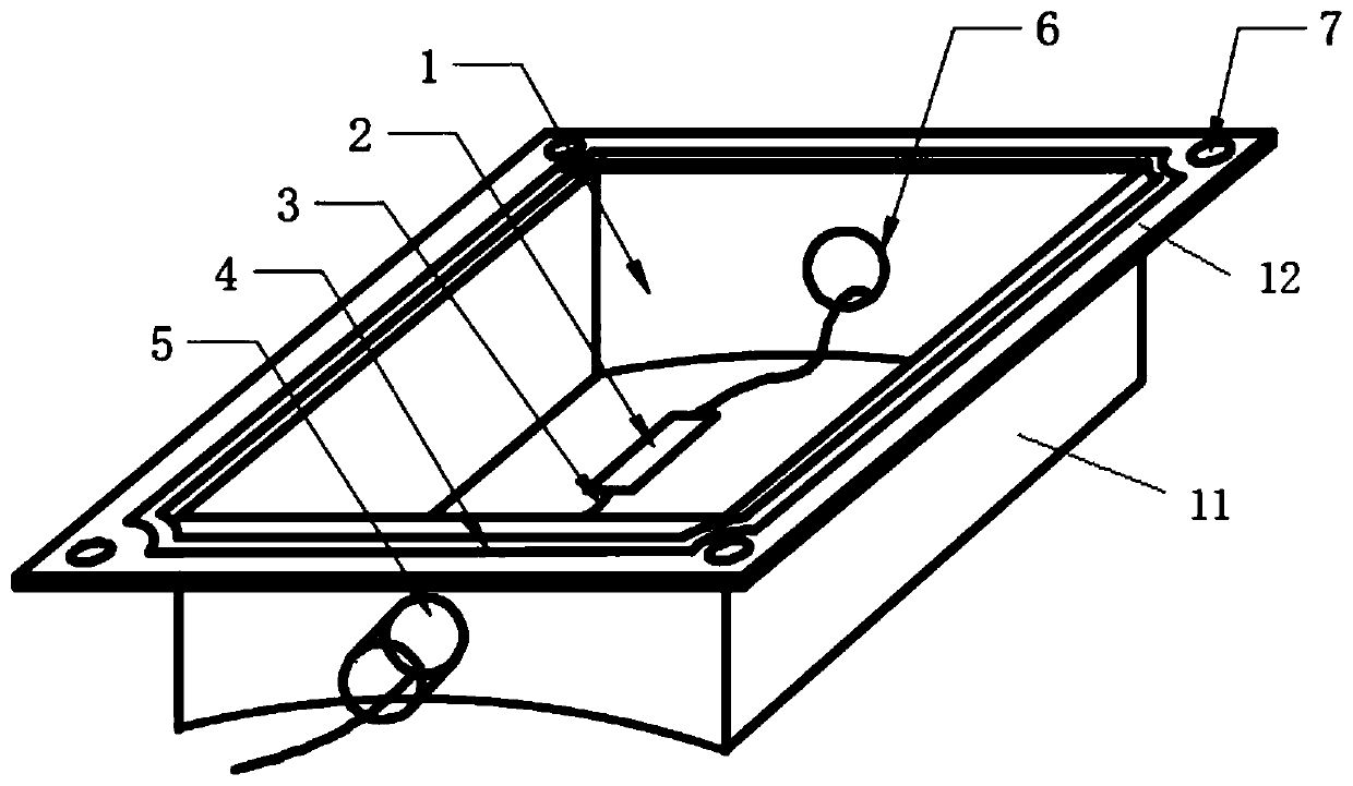
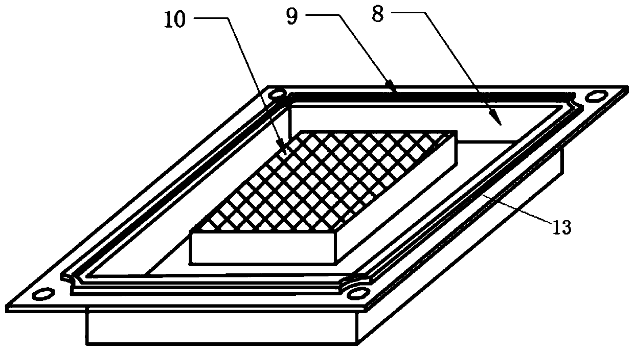
[0022] The present invention will be described below in conjunction with the accompanying drawings and embodiments. see figure 1 and figure 2 . The present invention is composed of a protective cover base 1 and a protective cover sealing cover 8, and is characterized in that: the protective cover base 1 is a rectangular structure without a bottom plate, so that the fiber grating strain sensor 2 is directly welded to the surface of the measured object, and the measurement accuracy is improved; The bottom of the upper and lower side plates of the cover base 1 is an arc structure, and the diameter of the arc is equal to the outer diameter of the platform leg at the installation position of the sensor in the splash zone, so that the base of the protective cover and the outer surface of the platform leg are seamlessly connected to achieve a full welding seal; protection The upper and lower side plates of the cover base 1 are respectively welded with an incoming line locking join...


PUM


Abstract

The invention relates to a protective device for a fiber grating strain sensor of an ocean platform splash zone. The protective device includes a protective cover base and a protective cover sealing cover, the protective cover base includes a side plate and a top outer edge plate covering the upper part of the side plate, an opening is formed in the bottom, the opening is matched with the installation position of the fiber grating strain sensor in shape, the protective cover base is connected with the installation position of the fiber grating strain sensor in a sealed mode, and the fiber grating strain sensor can directly be in contact with the measured surface; the side plate of the protective cover base is provided with an incoming line locking joint and an outgoing line locking joint which are connected with the side plate in a sealed mode; the protective cover sealing cover includes a filling box fixed to the inner surface and a sealing cover outer edge plate, and the filling boxis provided with a screen hole cover plate, and filled with an adsorbent capable of adsorbing water in the protective device; and the top outer edge plate of the protective cover base and the sealingcover outer edge plate are connected in a sealed mode. The protective device has the advantage of high reliability.

Description

technical field [0001] The invention relates to a protective placement of a fiber grating strain sensor, in particular to the protection of the sensor in the splash zone of an ocean platform. Background technique [0002] Offshore platform structural health monitoring technology has gradually been applied in the field. Fiber Bragg grating strain sensor, as one of the main sensors for health monitoring, is widely used due to its high precision, strong corrosion resistance and high reliability. However, the harsh marine environment with high corrosion and high salt spray makes the survival rate of the fiber grating strain sensor installation low, especially in the splash area of ​​the offshore platform. At the same time, data optical fibers often have disconnection accidents at the weak positions of the fusion fiber points, resulting in low reliability of the overall grating monitoring system. At present, in order to solve the problem that the fiber grating sensor is easily ...

Claims


Application Information

Patent Timeline
IPC IPC(8): G01B11/16
CPCG01B11/18
Inventor 黄焱朱本瑞田育丰万军
Owner TIANJIN UNIV
Learn More