Conveying device

A delivery device and proximal technology, applied in the field of medical devices, can solve problems such as inability to adjust, position deviation, etc., and achieve the effect of precise release and improved release quality

Pending Publication Date: 2020-03-10
SHANGHAI MICROPORT CARDIOFLOW MEDTECH CO LTD
View PDF0 Cites 3 Cited by
  • Summary
  • Abstract
  • Description
  • Claims
  • Application Information

AI Technical Summary

Problems solved by technology

With the traditional valve delivery method, that is, the sheath retracts and the stent self-expands to release, the outflow channel of the stent is released first, and the inflow channel is released later. However, in actual operation, it is difficult to accurately position the inflow channel to the annulus On the surface, there is often a position offset, and it cannot be adjusted after the offset is found

Method used


Image

  • Conveying device
  • Conveying device
  • Conveying device

Examples


Embodiment 1

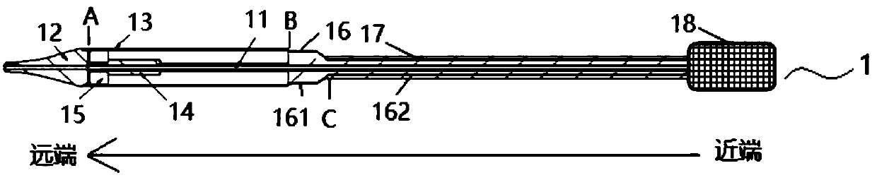
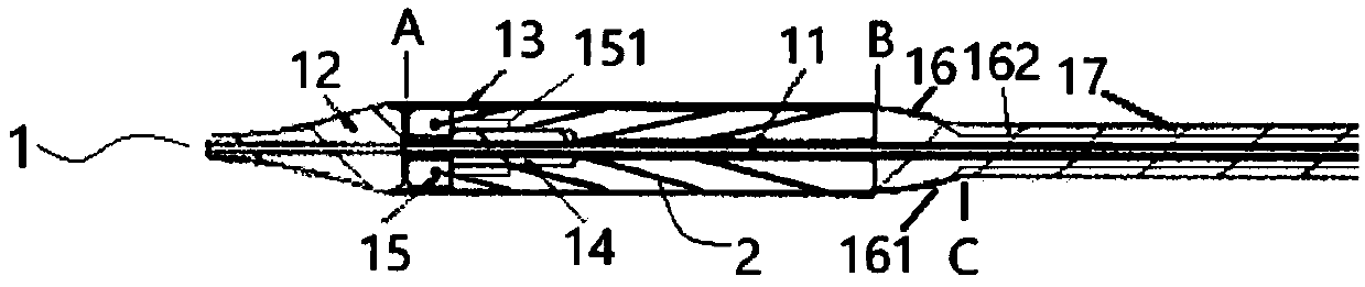
[0036] Such as figure 1 As shown, the delivery device 1 in this embodiment is composed of a catheter assembly and a handle 18 . Specifically, the catheter assembly includes: an inner core tube 11 , a guide head 12 , a sheath tube 13 , an inner tube 14 , a fixing head 15 , a transition part 16 and a bending control tube 17 .

[0037] Wherein, the proximal end of the inner core tube 11 is connected with the movable part of the inner core tube in the handle 18, so that the handle 18 can drive the axial movement of the inner core tube 11; in addition, the distal end of the inner core tube 11 is fixedly connected with the guide head 12 , the distal end of the sheath tube 13 is smoothly and fixedly connected to the proximal end of the guide head 12 at A, and the sheath tube 13 is sheathed outside the inner core tube 11 . In this way, after the inner core tube 11 is driven, it can drive the guide head 12 and the sheath tube 13 to move axially together.

[0038]Optionally, the guide...

Embodiment 2

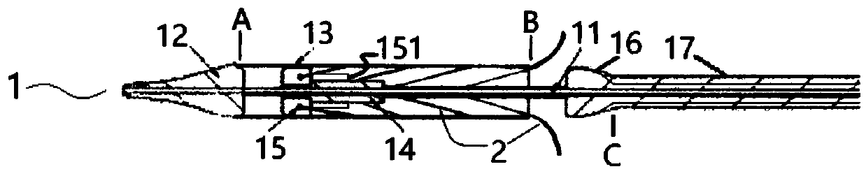
[0064]The transition part 16 in the first embodiment includes two parts, the transition part 161 and the conduit part 162 , which are connected to each other, and the structure is relatively complicated, and the implantation operation process of the implant body 2 is also relatively complicated. Based on this, if Figure 5 As shown, the transition part 16 has been modified in this embodiment, and another structure of the delivery device 1' for the implant is proposed.

[0065] Such as Figure 5 As shown, the transition part 16 in the present embodiment does not have the catheter part 162, only the transition part 161, in this case, the proximal end of the transition part 161 is directly and smoothly fixedly connected with the distal end of the bending control tube 17, through The axial movement of the bending control tube 17 controls the axial movement of the transition portion 161 . The structure of other parts of the delivery device 1' of the implant in this embodiment and...


PUM


Abstract

The invention discloses a conveying device. The device is used for loading, conveying and releasing an implant; and the conveying device comprises a handle, an inner core tube, a sheath tube and a guide head, the near end of the inner core tube is connected with an inner core tube movable part in the handle, and the guide head arranged at the far end of the inner core tube is fixedly connected with the far end of the sheath tube, wherein the near end refers to one end close to the handle, and the far end refers to one end far away from the handle. In the device, the far end of the sheath tubeis fixedly connected with the guide head, so that the conveying device can only load the implant through the near end of the sheath tube, when the implant is released, the sheath tube should move to the far end, that is, the sheath tube continues moving forward to the target position of the implant, instead of retreating towards the handle, so that problems such as unstable or even wrong implant release caused by retreating through a three-dimensional curved path of a sheath tube can be effectively avoided, and the release quality of the implant can be improved.

Description

technical field [0001] The invention relates to the technical field of medical instruments, in particular to a delivery device. Background technique [0002] For transcatheter mitral valve replacement (TMVR) surgery, accurate and reliable positioning of the valve stent is critical to the success of the procedure. The structure of the mitral valve is more complex than that of the aortic valve, and the shape of the valve ring is irregular. The multiple tendons in the ventricular chamber seriously interfere with the implantation and positioning of the interventional valve, and the intracavity pressure generated by ventricular contraction is very large. If the design of the positioning device is unreasonable, it will directly lead to a series of fatal complications. [0003] The sheath of the mitral valve delivery device needs to bear a large radial force of the stent, so a harder material must be used to avoid damage. The hard material and long length (50-70 mm) of the sheath...

Claims


Application Information

Patent Timeline
Patent Type & Authority Applications(China)
IPC IPC(8): A61F2/24
CPCA61F2/2466A61F2/2418A61F2/02A61F2/2436A61F2/9522A61F2/962A61F2/966A61F2/2427A61F2002/9505
Inventor 吴旭闻桂宝珠梅杰陈国明李雨
Owner SHANGHAI MICROPORT CARDIOFLOW MEDTECH CO LTD
Why Eureka
Try Eureka