

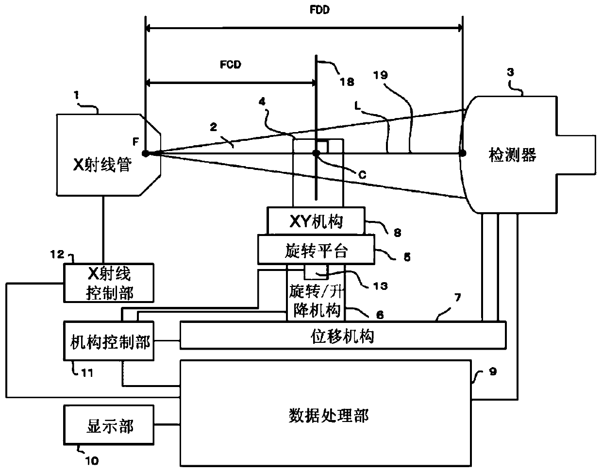
X-ray imaging device
A technology for imaging devices and X-rays, which can be used in measurement devices, radiological diagnostic equipment control, radiological diagnostic data transmission, etc., and can solve problems such as image blurring
- Summary
- Abstract
- Description
- Claims
- Application Information
AI Technical Summary
Problems solved by technology
Method used
Image

Examples
no. 2 Embodiment approach
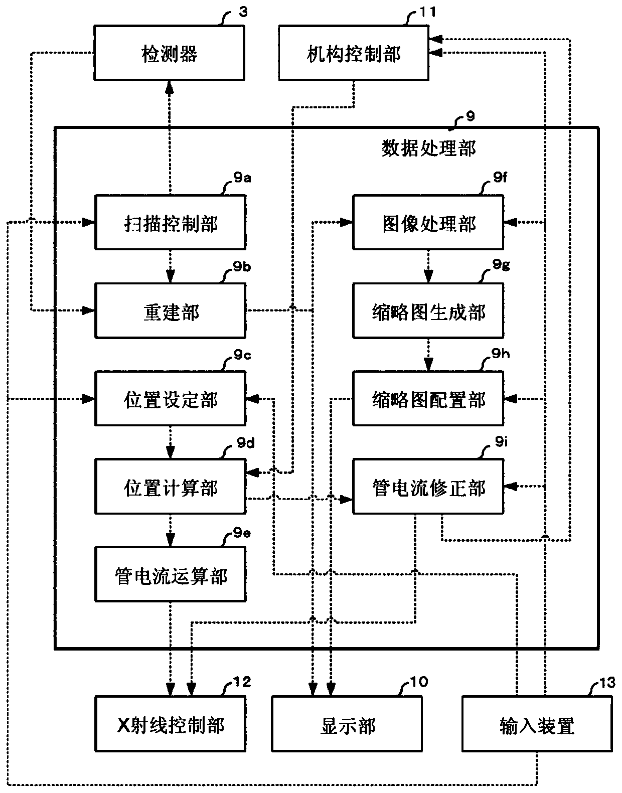
[0147] In the second embodiment, in addition to the processing of the first embodiment, a mechanical processing of changing the position of each part of the imaging device, that is, a hardware processing (hard) processing is added to the captured image, thereby obtaining a medium resolution or a SN ratio. Either of the enhanced images. Other configurations of the second embodiment are the same as those of the first embodiment. The same reference numerals are assigned to the same configuration as in the first embodiment, and description thereof will be omitted.
[0148] Such as Figure 4 As shown in the flowchart of FIG. 2 , in the second embodiment, it is selected whether to perform resolution or SN ratio correction processing on the image captured in the first embodiment ( S51 ). The selection is performed by the operator outputting a predetermined command from the input device 13 to the mechanism control unit 11 . If the correcting process is selected (Yes (YES) in S51), ...
no. 3 Embodiment approach
[0153] In the third embodiment, instead of the resolution correction or SN ratio correction processing in the second embodiment, the image processing unit 9f performs software-based image processing such as contour enhancement or noise removal on the captured image, thereby obtaining improved visibility. Image. Other configurations of the third embodiment are the same as those of the second embodiment. The same reference numerals are assigned to the same configuration as in the second embodiment, and description thereof will be omitted.
[0154] Such as Figure 5As shown in the flow chart of , in the third embodiment, it is selected whether to perform correction processing of edge enhancement or noise removal on the image captured in the first embodiment (S53). The selection is performed by the operator outputting a predetermined command from the input device 13 to the mechanism control unit 11 . If the correction process is selected (Yes in S53), the mechanism control unit...
PUM
 Abstract
Description
Claims
Application Information