Integrated proximity switch, proximity switch system and proximity switch manufacturing method
A technology of proximity switch and manufacturing method, which is applied in the field of proximity switch system and proximity switch manufacturing, and integrated proximity switch, which can solve the problems that Hall proximity switches cannot realize fully automatic standard production and large volume, and achieve easy automatic standardized production , high integration, high precision and the effects of high integration characteristics
- Summary
- Abstract
- Description
- Claims
- Application Information
AI Technical Summary
Problems solved by technology
Method used
Image

Examples
Embodiment 1
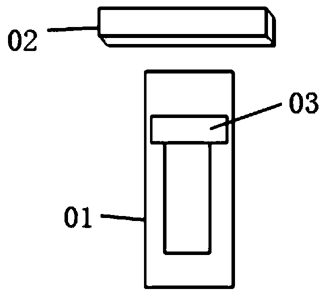
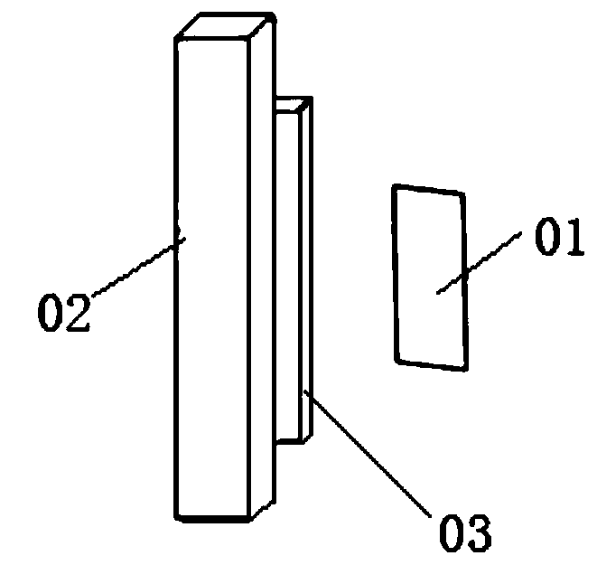
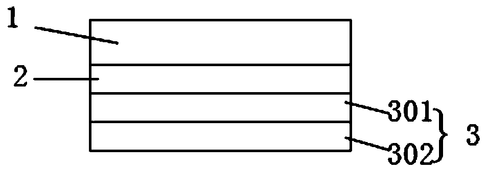
[0044] Such as Figure 4 An integrated proximity switch system includes a magnetic object 6 and an integrated proximity switch 5; the magnetic object 6 is arranged opposite to the integrated proximity switch 5, and a gap is left between the magnetic object 6 and the integrated proximity switch 5. Such as image 3 , wherein the integrated proximity switch 5 includes a Hall integrated circuit 1, and a magnetic thin film layer 3 arranged on the back of the Hall integrated circuit 1, and an insulating layer 2 is arranged between the Hall integrated circuit 1 and the magnetic thin film layer 3, so The N pole of the magnetic thin film layer 3 is on the top and the S pole is on the bottom or the S pole is on the top and the N pole is on the bottom. The upper and lower positions of the N pole magnetic film layer 301 and the S pole magnetic film layer 302 of the magnetic film layer 3 are not limited; 1. The insulating layer 2 and the magnetic thin film layer 3 are packaged together. T...
Embodiment 2
[0047] Such as Figure 5 An integrated proximity switch system includes a magnetic object 6 and an integrated proximity switch 5; the magnetic object 6 is arranged opposite to the integrated proximity switch 5, and a gap is left between the magnetic object 6 and the integrated proximity switch 5. Wherein, the integrated proximity switch 5 includes a Hall integrated circuit 1, and a magnetic thin film layer 3 arranged on the back side of the Hall integrated circuit 1, and an insulating layer 2 is arranged between the Hall integrated circuit 1 and the magnetic thin film layer 3. The N pole of the magnetic film layer 3 is on the top and the S pole is on the bottom or the S pole is on the top and the N pole is on the bottom. The upper and lower positions of the N pole magnetic film layer 301 and the S pole magnetic film layer 302 of the magnetic film layer 3 are not limited; , the insulating layer 2 and the magnetic film layer 3 are packaged in one body, the insulating layer 2 is ...
Embodiment 3
[0050] An integrated proximity switch system includes a magnetic object 6 and an integrated proximity switch 5; the magnetic object 6 is arranged opposite to the integrated proximity switch 5, and a gap is left between the magnetic object 6 and the integrated proximity switch 5. Such as Figure 8 , wherein the integrated proximity switch 5 includes a Hall integrated circuit 1 and a magnet 4 arranged on the back of the Hall integrated circuit 1; an insulating layer 2 is provided between the Hall integrated circuit 1 and the magnet 4; the magnet 4 The N-pole and S-pole connections of the poles are perpendicular to the Hall integrated circuit 1; the Hall integrated circuit 1, the insulating layer 2 and the magnet 4 are packaged in one body. The thickness of the magnet 4 is 0.1 mm, and the insulating layer 2 is a silicon dioxide insulating layer with a thickness of 1000 nm.
[0051] This integrated proximity switch system can also be similar to the embodiment-widely used in vario...
PUM
| Property | Measurement | Unit |
|---|---|---|
| thickness | aaaaa | aaaaa |
| thickness | aaaaa | aaaaa |
| thickness | aaaaa | aaaaa |
Abstract
Description
Claims
Application Information
 - R&D
- Intellectual Property
- Life Sciences
- Materials
- Tech Scout
- Unparalleled Data Quality
- Higher Quality Content
- 60% Fewer Hallucinations
Browse by: Latest US Patents, China's latest patents, Technical Efficacy Thesaurus, Application Domain, Technology Topic, Popular Technical Reports.
© 2025 PatSnap. All rights reserved.Legal|Privacy policy|Modern Slavery Act Transparency Statement|Sitemap|About US| Contact US: help@patsnap.com