Underwater grouting measurement device and method for offshore wind power jacket foundation by pile-first method

An offshore wind power and underwater grouting technology, which is used in infrastructure engineering, infrastructure testing, construction, etc., can solve problems such as the inability to observe the amount of grouting in real time, the leakage of the grouting material to the steel pipe pile, and the inability to determine the leakage of the grouting. , to achieve the effect of solving the difficulty of grouting amount monitoring, less material consumption, saving manpower, material resources and time

Inactive Publication Date: 2020-03-17
ZHEJIANG UNIV
View PDF7 Cites 2 Cited by
  • Summary
  • Abstract
  • Description
  • Claims
  • Application Information

AI Technical Summary

Problems solved by technology

This method has many defects: 1) Generally, the water depth of the jacket is deep, and divers cannot observe underwater for a long time, and multiple divers need to take turns to enter the water, which is costly; 2) The grouting space is basically in a closed space, and it is impossible to observe the specific grouting in real time It can only be judged after the grouting material overflows from the gap at the upper end, resulting in a large waste of material; 3) During the grouting process, the grouting material leaks from the bottom of the grouting space to the steel pipe pile, and the current operation cannot determine whether the grout is leaking

Method used


Image

  • Underwater grouting measurement device and method for offshore wind power jacket foundation by pile-first method
  • Underwater grouting measurement device and method for offshore wind power jacket foundation by pile-first method
  • Underwater grouting measurement device and method for offshore wind power jacket foundation by pile-first method

Examples


Embodiment Construction

[0019] The present invention is described below in conjunction with accompanying drawing and specific embodiment:

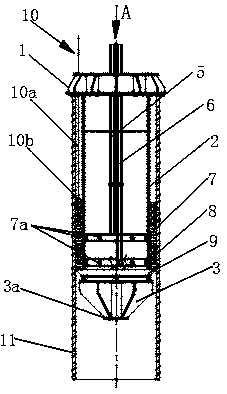
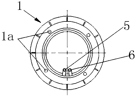
[0020] figure 1 , 2 , 3 shows a structural diagram of an underwater grouting measurement device for offshore wind power jacket foundations using the pile-first method. This underwater grouting measurement device for the offshore wind power jacket foundation of the pile-first method includes a flange 1, a pile leg 2 and a conical head 3, and the conical head 3 is fixed at the end of the pile leg 2 to form a plurality of A rib is connected with the circular plate 3a; it also includes the first grouting pipe 6, the second grouting pipe 5, the first annular cavity 7 and the second annular cavity 8 arranged on the inner wall of the leg 2, the measuring mechanism 10 and the sealing ring 9. Two grouting pipes run through the flange 1 and extend to the inside of the leg 2. The first grouting pipe 6 is provided with a first upper grouting pipe support rod 6a, a first l...


PUM


Abstract

The invention discloses an underwater grouting measurement device and method for an offshore wind power jacket foundation by a pile-first method, and belongs to the technical field of offshore wind power engineering. The underwater grouting measurement device for the offshore wind power jacket foundation by the pile-first method comprises a flange plate, a pile leg, a conical head, a first grouting pipe, a second grouting pipe, a first annular cavity, a second annular cavity, a measurement mechanism and a sealing ring, wherein the two grouting pipes penetrate through the flange plate and extend into the pile leg; the first annular cavity and the second annular cavity are formed in the lower part of the inner side of the pile leg; the sealing ring sleeves the outer side of the bottom of thepile leg; and the measurement mechanism comprises a scale mark post and a buoyancy ball. The device is simple in structure, low in material consumption and reusable. The grouting measurement method is simple and convenient in measurement process, does not damage a pile, is short in measurement time, and saves a large amount of time and cost. The position of a grouting material can be known by observing the scale of the mark post on the water surface, and whether slurry leakage occurs or not is monitored in real time, so that underwater observation by a diver can be reduced or even avoided.

Description

technical field [0001] The invention relates to an underwater grouting measurement device and a measurement method for an offshore wind power jacket foundation using a pile-first method, and belongs to the technical field of offshore wind power engineering. Background technique [0002] The current pile-first offshore wind power jacket wind turbine foundation is mainly composed of steel piles and jacket structure. During the installation process, the steel piles are first driven into the seabed, and then the jacket is hoisted and its legs are inserted into the seabed. In the steel piles, in order to ensure the mutual connection between the structures, it is necessary to fill the space between the jacket legs and the steel piles with grouting materials. After the grouting material solidifies, it can ensure that the jacket legs and the steel piles are connected together to bear Wind turbines, waves and other loads. [0003] Since the grouting space is basically in the underwa...

Claims


Application Information

Patent Timeline
Patent Type & Authority Applications(China)
IPC IPC(8): E02D33/00
CPCE02D33/00
Inventor 朱嵘华田振亚孙香屈励博胡彬绳结竑徐晓臻徐宏黎鹏飞
Owner ZHEJIANG UNIV
Why Eureka
Try Eureka