Smelting device for metal material processing

A metal material and discharge port technology, which is applied to the field of smelting devices for metal material processing, can solve the problems of inconvenient slag discharge and difficult movement of the smelting device, and achieve the effects of solving the inconvenient slag discharge, speeding up the melting speed and improving the smelting efficiency.

Inactive Publication Date: 2020-03-17
ZHUZHOU TIANQIAO SHUNCHEN COAL PREPARATION MACHINERY
View PDF0 Cites 6 Cited by
  • Summary
  • Abstract
  • Description
  • Claims
  • Application Information

AI Technical Summary

Problems solved by technology

[0003] The existing smelting device is inconvenient to discharge slag and difficult to move

Method used


Image

  • Smelting device for metal material processing
  • Smelting device for metal material processing
  • Smelting device for metal material processing

Examples


Embodiment 1

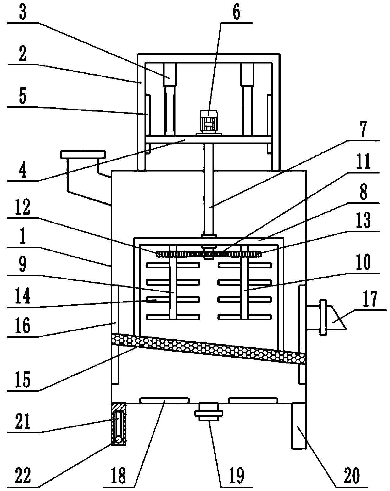
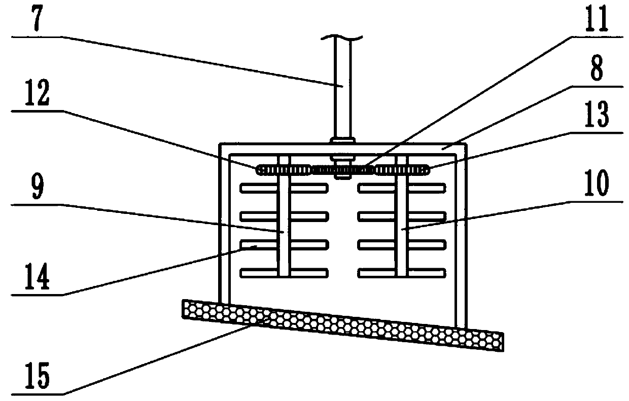
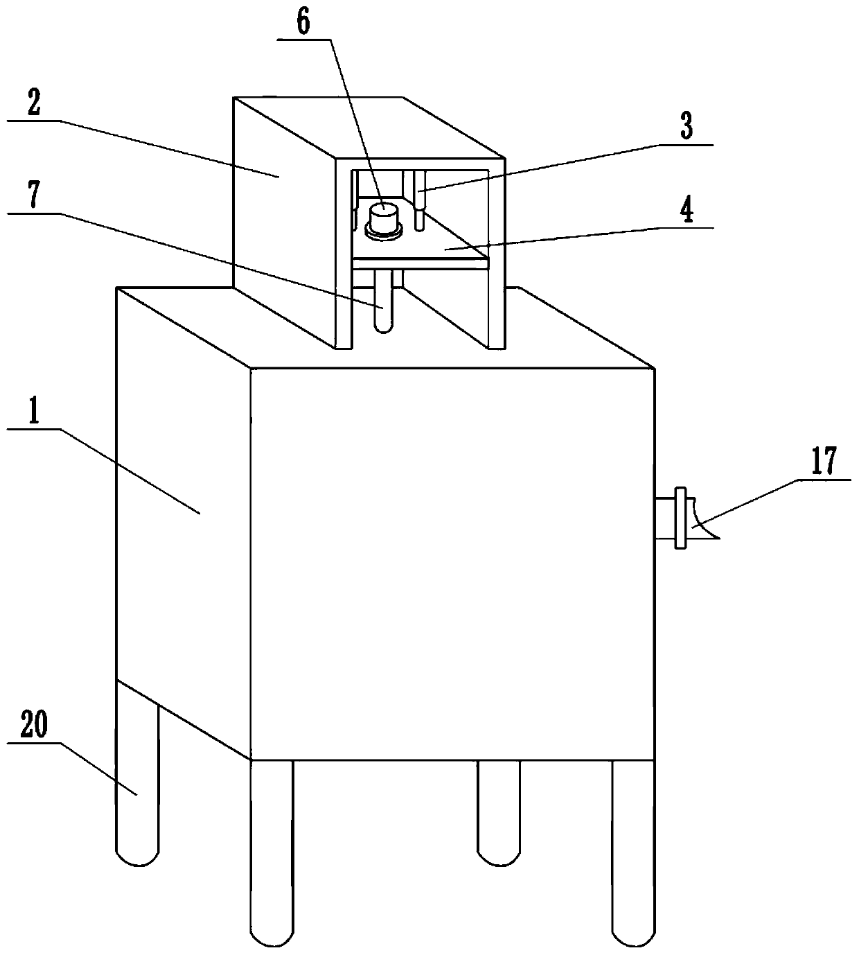
[0022] see Figure 1-3 , In the embodiment of the present invention, a smelting device for metal material processing includes a casing 1, a fixing frame 2, an electric heating plate 18 and a discharge port 19. A feeding port is installed above the side wall of the casing 1, and the feeding port is detachably installed. There is a cover plate, the raw material to be smelted is put into the casing 1 through the feeding port, the top of the casing 1 is fixedly connected with a fixing frame 2, a lifting plate 4 is installed inside the fixing frame 2, and a slide rail 5 is installed on the inner side wall of the fixing frame 2 , both ends of the lifting plate 4 are embedded in the sliding rail 5, the lifting plate 4 can slide up and down along the sliding rail 5, the upper surface of the lifting plate 4 is fixedly connected with a first telescopic mechanism 3, and the first telescopic mechanism 3 is an electric hydraulic telescopic cylinder , the top of the first telescopic mechani...

Embodiment 2

[0024] On the basis of Embodiment 1, the bottom of the housing 1 is fixedly connected with a supporting foot 20, the bottom of the supporting foot 20 is provided with a cavity, and a second telescopic mechanism 21 is installed inside the cavity, and the second telescopic mechanism 21 is an electro-hydraulic telescopic rod. A universal wheel 22 is installed on the lower end of the second telescopic mechanism 21. When the device needs to be moved, the second telescopic mechanism 21 is controlled to extend to drive the universal wheel 22 to move downward, so that the universal wheel 22 is connected to the ground. By jacking up the device, the device can be easily pushed to move.

[0025] Combined with Embodiment 1 and Embodiment 2, the working principle of the present invention is: during the smelting operation, the molten metal in the casing 1 is heated by the electric hot plate 18, and the metal to be smelted is put into the casing 1 through the feeding port, Start the motor 6,...


PUM


Abstract

The invention relates to the field of smelting equipment. More particularly, the present invention relates to a smelting device for metal material processing. The smelting device comprises a shell, afixed frame, an electric heating plate and a discharge port; the top of the shell is fixedly connected with the fixed frame; a lifting plate is mounted in the fixed frame; a sliding rail is installedon the inner side wall of the fixed frame; two ends of the lifting plate are embedded into the sliding rail; the upper surface of the lifting plate is fixedly connected with a first telescopic mechanism; the upper surface of the lifting plate is fixedly connected with a motor; the shaft extension end of the motor is fixedly connected with a rotating shaft; a lifting frame is mounted at the lower end of the rotating shaft; the rotating shaft is rotationally connected with the lifting frame; a left stirring shaft and a right stirring shaft are mounted in the lifting frame. In the smelting process, the stirring rod is used for stirring molten metal, so the metal smelting speed is increased, and the smelting efficiency is improved; a sieve plate is used for collecting residues which cannot besmelted, and the residues can be discharged through the slag discharging opening by controlling the sieve plate to ascend and descend, so great convenience is achieved; and the device can be conveniently pushed to move by controlling the universal wheels to ascend and descend.

Description

technical field [0001] The invention relates to the field of smelting equipment, more particularly, to a smelting device for metal material processing. Background technique [0002] Smelting is a pyrometallurgical process in which metal materials and other auxiliary materials are put into a heating furnace for melting and tempering, and the materials undergo certain physical and chemical changes in the high-temperature furnace to produce crude metal or metal concentrates and slag. In addition to concentrate, calcine, sinter, etc., the charge of the charge sometimes needs to be added with a flux to make the charge easy to melt, and a reducing agent for a certain reaction. In addition, in order to provide the necessary temperature, it is often necessary to add fuel for combustion. And send air or oxygen-enriched air. [0003] The existing smelting device is inconvenient to discharge slag and difficult to move. SUMMARY OF THE INVENTION [0004] The purpose of the present in...

Claims


Application Information

Patent Timeline
Patent Type & Authority Applications(China)
IPC IPC(8): F27D27/00F27D3/15
CPCF27D3/1545F27D27/00
Inventor 凌英黄亚飞刘远力
Owner ZHUZHOU TIANQIAO SHUNCHEN COAL PREPARATION MACHINERY
Why Eureka
Try Eureka