Unmanned aerial vehicle visual navigation positioning method based on laser ray assistance

A technology of visual navigation and positioning method, which is applied in the field of visual navigation and can solve the problems that the processor cannot run in real time, the price of lidar is expensive, and the volume of lidar is large.

Active Publication Date: 2020-03-17
NANJING UNIV OF AERONAUTICS & ASTRONAUTICS +1
View PDF6 Cites 5 Cited by
  • Summary
  • Abstract
  • Description
  • Claims
  • Application Information

AI Technical Summary

Problems solved by technology

[0007] However, the disadvantage of method 1 is that GNSS is only suitable for open scenes with strong GNSS signals, and cannot be used in indoor environments; the disadvantage of method 2 is that the lidar is too large to be installed on small drones, and the Radar is expensive; the disadvantage of method 3 is that the combined navigation algorithm of visual and inertial sensor

Method used


Image

  • Unmanned aerial vehicle visual navigation positioning method based on laser ray assistance
  • Unmanned aerial vehicle visual navigation positioning method based on laser ray assistance
  • Unmanned aerial vehicle visual navigation positioning method based on laser ray assistance

Examples


Embodiment Construction

[0063] Embodiments of the invention are described in detail below, examples of which are illustrated in the accompanying drawings. The embodiments described below by referring to the figures are exemplary only for explaining the present invention and should not be construed as limiting the present invention.

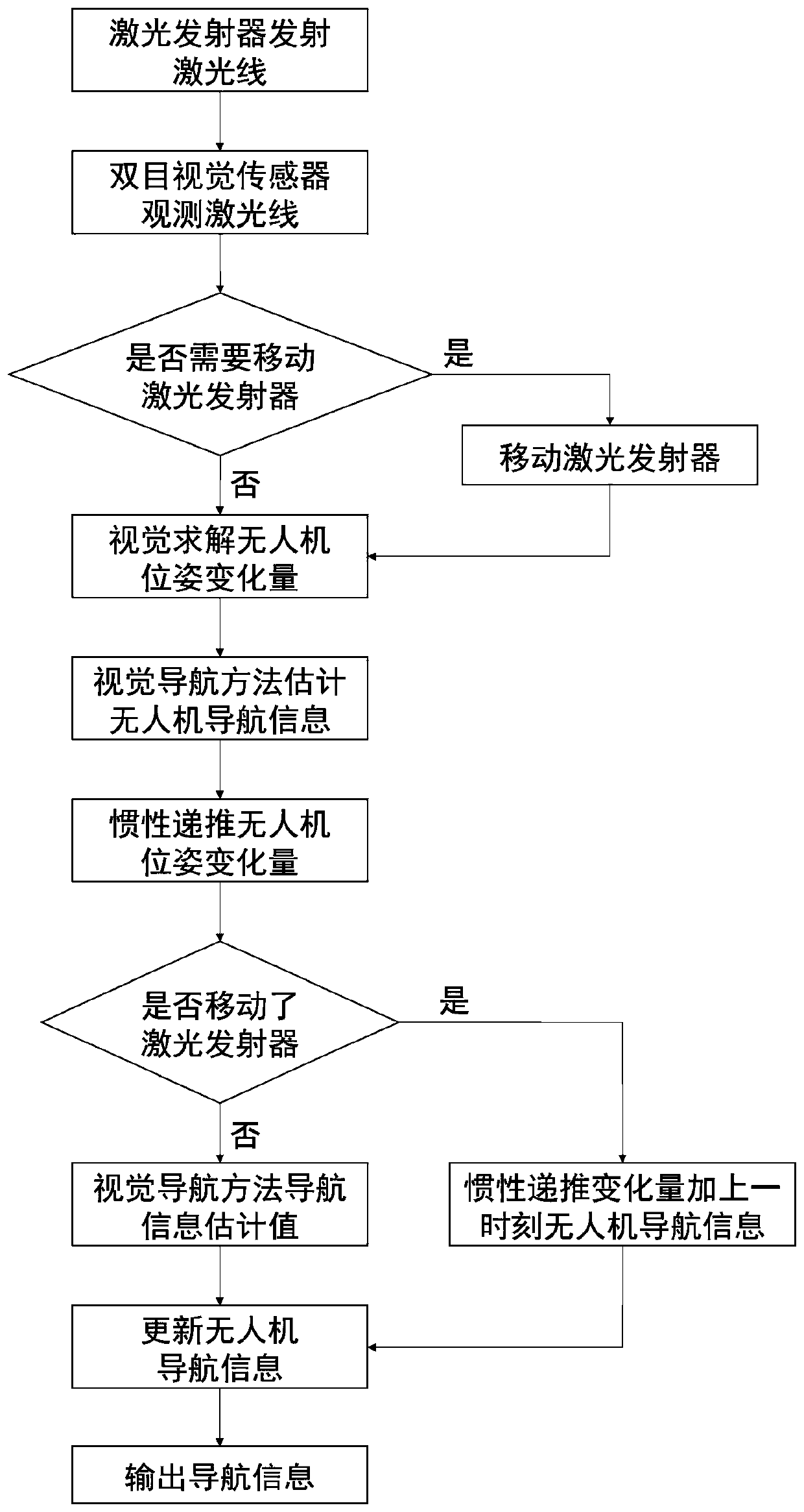
[0064] The flow process of the inventive method is as figure 1 As shown, the specific steps are as follows:

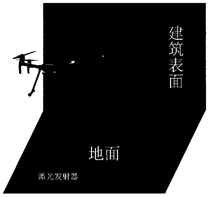
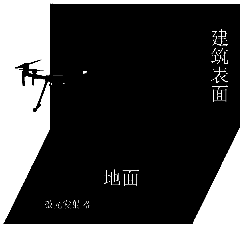
[0065] Step 1: A pre-coded laser line is emitted through a laser transmitter. The laser line is projected on the surface of the building. The laser transmitter can be installed on the ground or carried by another drone. For example, figure 2 and image 3 The medium laser transmitter is installed on the ground, Figure 4 The medium laser transmitter is carried on another drone. Moreover, the laser lines emitted by the laser transmitter can be projected onto the building surface to form evenly distributed laser lines in a large range. For example, figure 2...


PUM


Abstract

The invention discloses an unmanned aerial vehicle visual navigation positioning method based on laser ray assistance. The unmanned aerial vehicle visual navigation positioning method comprises the steps of utilizing a laser emitter to emit laser rays in a regular shape, projecting the laser rays onto the surface of a building, observing the laser rays by means of a binocular vision sensor carriedon an unmanned aerial vehicle, and carrying out visual navigation by taking the laser rays as characteristics, thereby providing navigation information for the unmanned aerial vehicle. A traditionalvisual navigation method has high requirements for environment features and light rays, and the unmanned aerial vehicle visual navigation positioning method can improve visual navigation precision inthe environment with sparse features and dark light rays in a laser ray assisting mode.

Description

technical field [0001] The invention relates to a laser line-assisted visual navigation and positioning method for an unmanned aerial vehicle, belonging to the technical field of visual navigation. Background technique [0002] Generally, the most common way for UAVs to navigate and locate in environments with sparse features and dark light is to estimate the navigation information of UAVs based on the data of accelerometers and gyroscopes based on inertial sensors. However, the error of the inertial navigation system will Accumulated over time, navigation accuracy can become poor after long hours of work. [0003] In order to solve the above problems, there are three existing improved navigation and positioning methods for UAVs in sparsely featured and dark environments: [0004] Method 1: Add a Global Navigation Satellite System (Global Navigation Satellite System, GNSS) module to the UAV, and use the high positioning accuracy of GNSS to correct the error of the inertial ...

Claims


Application Information

Patent Timeline
IPC IPC(8): G01C21/20G01C21/18G01C21/16G01C21/00G01C15/00G01C11/08
CPCG01C21/20G01C21/18G01C21/165G01C21/005G01C15/004G01C11/08
Inventor 吕品杨子寒赖际舟蔡小飞闫洪林石庆仪
Owner NANJING UNIV OF AERONAUTICS & ASTRONAUTICS
Why Eureka
Try Eureka