FANUC encoder cable tester and test method

A test method and tester technology, applied in the direction of continuity test, instrument, measurement power, etc., can solve the problems of signal attenuation and signal interference that cannot be tested, large difference between dynamic and static, cumbersome test process, etc., to improve test efficiency, The effect of low manufacturing cost, improved maintenance efficiency and quality

Inactive Publication Date: 2020-03-17
INNER MONGOLIA FIRST MACHINERY GRP
View PDF6 Cites 1 Cited by
  • Summary
  • Abstract
  • Description
  • Claims
  • Application Information

AI Technical Summary

Problems solved by technology

Solve the sudden and sporadic faults of CNC machine tools caused by cable damage; overcome the cumbersome test process of traditional test methods, the large difference between dynamic and static, signal attenuation and interference between signals cannot be tested, and it is difficult to judge and unclear, etc. question

Method used


Image

  • FANUC encoder cable tester and test method
  • FANUC encoder cable tester and test method

Examples


Embodiment Construction

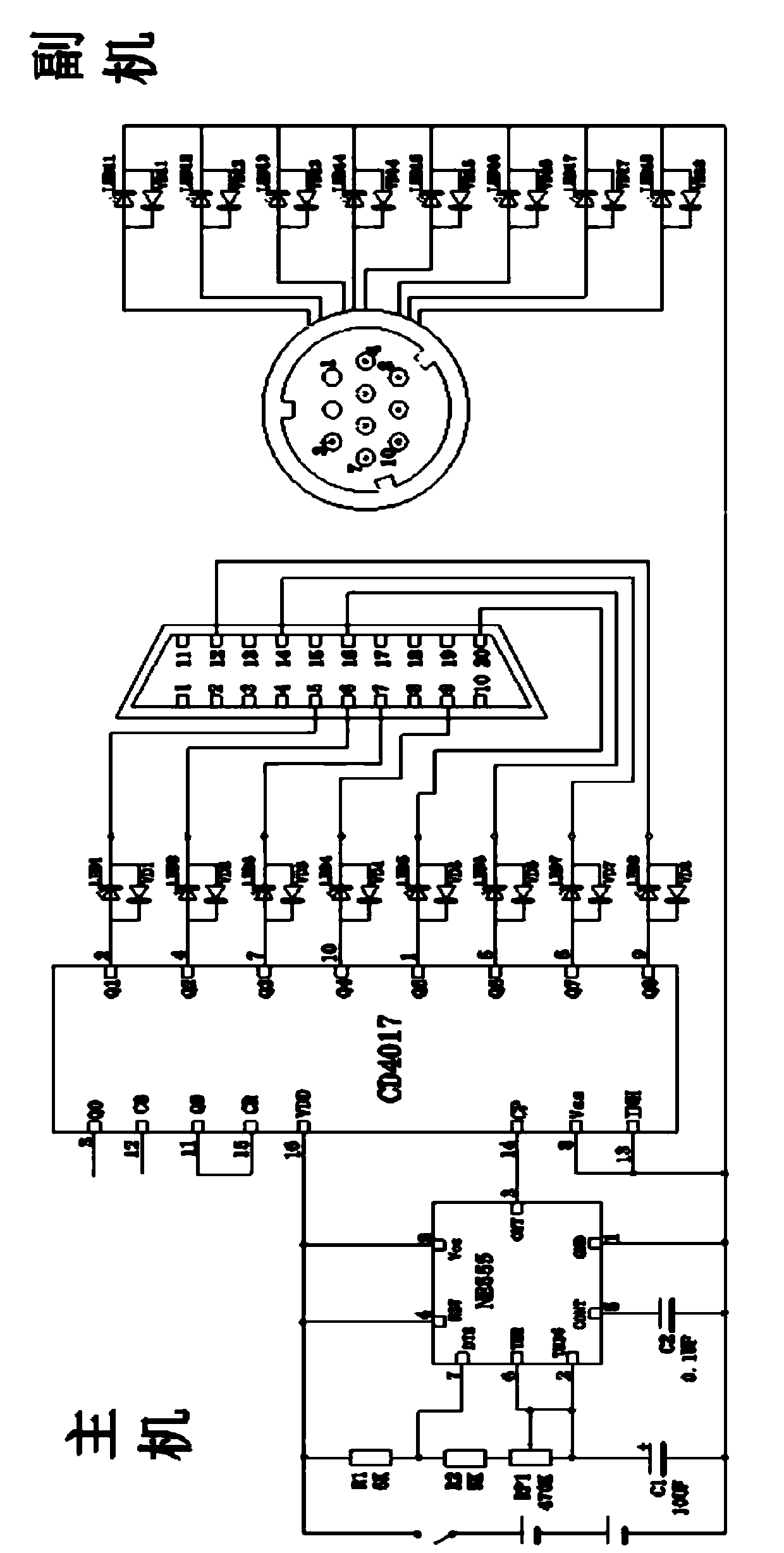
[0036] The invention is a portable FANUC encoder cable tester, which includes: a cable to be tested and sockets at both ends, a power supply battery, a multivibrator, a CD4017 counter chip, a power switch, and LED light-emitting diodes.

[0037] The multivibrator is composed of NE555 chip, resistors R1, R2, potentiometer RP1, capacitors C1, C2; one end of potentiometer RP1 is connected to resistor R2, the other end is connected to the middle tap end, and one end of capacitor C1 and NE555 Chip 6-pin (THR threshold) and 2-pin (TRIG trigger) are connected, the other end of resistor R2 is connected to one end of resistor R1, 7-pin of NE555 chip (DIS discharge), one end of capacitor C2 is connected to 5-pin of NE555 chip (CONT control) Connect, the 1 pin (GND) of the NE555 chip is connected to the other end of the capacitor C1 and the other end of C2, and connected to GND, and the other end of the resistor R1 is connected to the 4 pin (RST reset) and 8 pin (Vcc power supply) of the ...


PUM


Abstract

The invention provides an FANUC encoder cable tester and a test method, which belong to the technical field of cable testing, can solve sudden and accidental faults of a numerical control machine toolcaused by cable damage, overcome the problems that a traditional testing method is tedious in testing process, large in dynamic and static difference, incapable of testing signal attenuation and interference between signals, not easy to judge, unclear in judgment and the like, and realize efficient maintenance of numerical control equipment. The FANUC encoder cable tester is characterized by comprising a multivibrator, a CD4017 counter chip, a power switch and an LED light emitting diode. The testing method adopting the FANUC encoder cable tester comprises the steps of: adjusting an RP1 potentiometer to enable the multivibrator to generate clock pulses with adjustable frequency, and indicating that a state of a cable to be tested is normal when two sets of LED light emitting diodes are lightened. Compared with the existing examples, the FANUC encoder cable tester can obviously improve the encoder cable maintenance field test efficiency, makes judgment on encoder faults more intuitive,precise and efficient by adjusting the LED lighting period, and can greatly improve the field maintenance efficiency.

Description

technical field [0001] The invention belongs to the technical field of cable testing, and relates to an encoder cable testing instrument. Background technique [0002] There are mainly two types of existing cable testing instruments: [0003] Example 1: Patent No.: CN 106646083 A, Name: A servo encoder cable tester and its testing method. This patented technology aims to solve the traditional Mitsubishi MR-J3-A servo encoder full range of cable detection technology: it is based on the point-to-point interface test of the multimeter. Under the premise of mass testing, the test process is cumbersome and error-prone. It takes a lot of time in the production testing process. The specific operation is to press the SW-SPST trigger key to trigger. After the single-chip microcomputer receives the trigger signal, the IO port of the single-chip microcomputer outputs a high level to drive the connectivity of the detection circuit. Cycle 6 times (the cycle time is fixed), and the cor...

Claims


Application Information

Patent Timeline
IPC IPC(8): G01R31/54G01R31/58G01R31/00
Inventor 王贵勇张爱国马强郭永杰王晓永刘海生汤若奇常青毛晓宇白光明陈通赵军吕岩李晓杰武春光韩阳蔺璇郭强宋孝微李雪童王晓杰赵菲雷瑜嘉李平郝春宝李成荣
Owner INNER MONGOLIA FIRST MACHINERY GRP
Why Eureka
Try Eureka