Light source system and projection device

A light source system and light device technology, applied in the field of optics, to achieve the effect of improving space utilization and reducing volume

Active Publication Date: 2021-05-11
APPOTRONICS CORP LTD
View PDF8 Cites 0 Cited by
  • Summary
  • Abstract
  • Description
  • Claims
  • Application Information

AI Technical Summary

Problems solved by technology

Laser light source for emitting laser light

Method used


Image

  • Light source system and projection device
  • Light source system and projection device
  • Light source system and projection device

Examples


no. 1 example

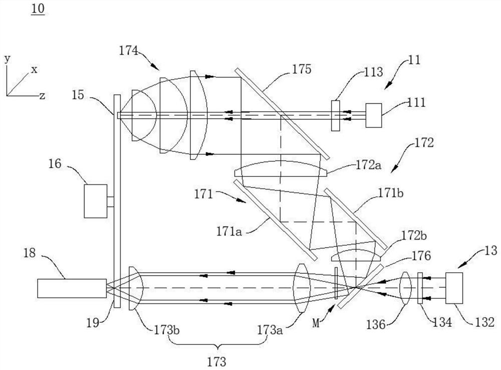
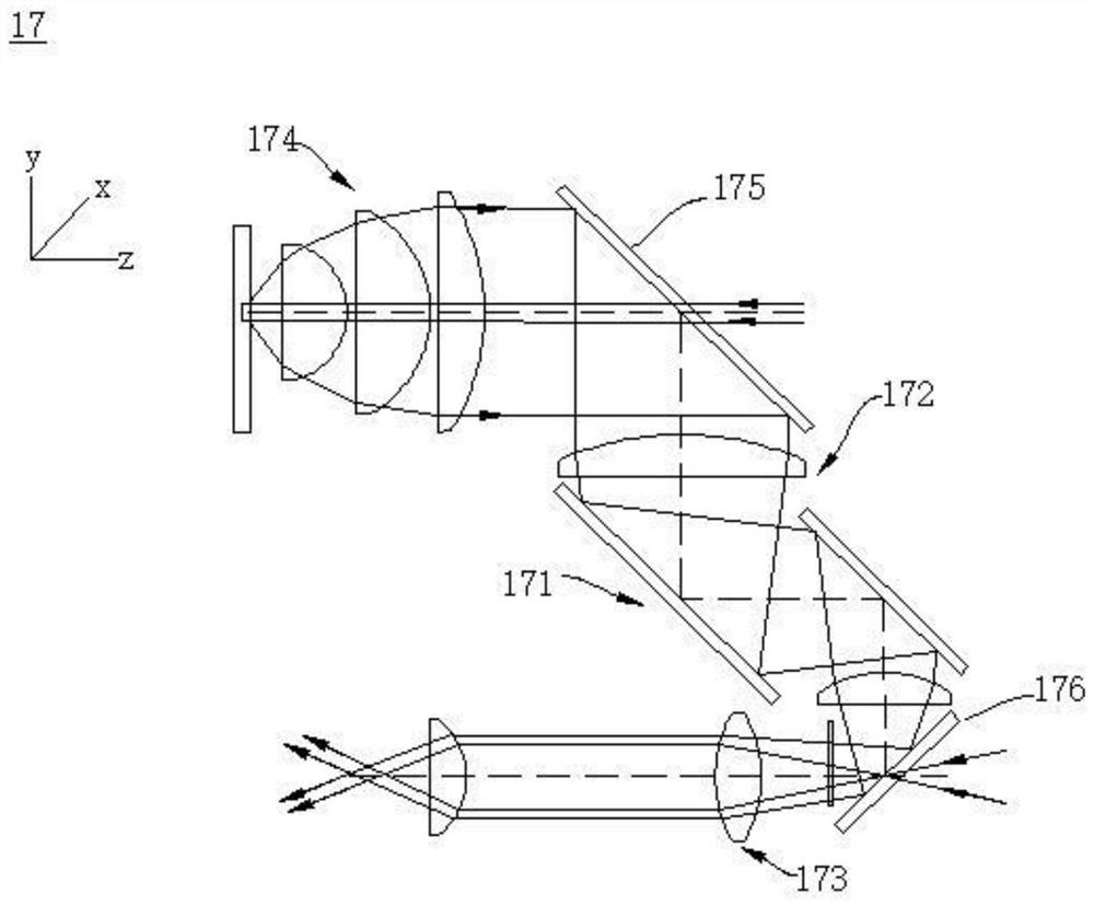
[0021] Please also refer to Figure 1 to Figure 4 , The light source system 10 provided in this embodiment includes: a laser light source 11 , a supplementary light source 13 , a wavelength conversion device 15 and an imaging subsystem 17 . The laser light source 11 is used to emit laser light. The supplementary light source 13 is used to emit supplementary light. The wavelength conversion device 15 is used to convert the laser light into the accepted light. The imaging subsystem 17 is used to form the first optical imaging beam, the supplementary optical imaging beam and the mixed optical imaging beam. The mixed light imaging beam is formed by combining the first light imaging beam and the supplementary light imaging beam. The first light imaging light beam, the supplementary light imaging light beam and the mixed light imaging light beam are transmitted in the imaging subsystem 17 and respectively form the first light imaging light path, the supplementary light imaging li...

no. 2 example

[0049] see Figure 5 , different from the first embodiment, the reflective assembly 271 in the light source system 20 provided by this embodiment is also used to reflect the mixed light imaging beam, the first convex lens 272a is perpendicular to the optical axis of the second convex lens 272b, and the third convex lens 273a The optical axis of the fourth convex lens 273b is perpendicular to the optical axis of the third convex lens 273a and the optical axis of the first convex lens 272a may be parallel. The first reflection unit 271a is located between the first convex lens 272a and the second convex lens 272b, and the second reflection unit 271b is located between the third convex lens 273a and the fourth convex lens 273b, that is, the first reflection unit 271a is located between the first convex lens 272a and the second convex lens 272a. Between the first light imaging optical path between the convex lenses 272b, the second reflection unit 271b is located between the mixed...

no. 3 example

[0052] see Figure 6 , the difference from the first embodiment is that the first reflection unit 371a and the second reflection unit 371b in the light source system 30 provided by this embodiment are arranged opposite to each other, that is, the reflection surfaces of the first reflection unit 371a and the second reflection unit 371b face each other. set up.

[0053] In the light source system 30 provided in this embodiment, the optical path is folded by arranging the first reflection unit 371a and the second reflection unit 371b in the first relay assembly 372, and the relative arrangement of the first reflection unit 371a and the second reflection unit 371b, The optical path is rationally utilized, the transmission distance of the received light in the y-axis direction is shortened, the length or diameter of the wavelength conversion device 35 in the y-axis direction is reduced, the wavelength conversion device 35 is miniaturized and the first light imaging optical path Th...


PUM


Abstract

The invention provides a light source system and a projection device. The light source system includes: a laser light source, a supplementary light source, a wavelength conversion device and an imaging subsystem. Laser light source for emitting laser light. A fill light that emits fill light. The wavelength conversion device is used to convert the laser light into the subject light, and emit the first light including the subject light and the laser light. The imaging subsystem is used to form the first light imaging beam, the supplementary light imaging beam and the mixed light imaging beam; the imaging subsystem includes a light combination device and a reflection assembly, and the light combination device is placed between the first light imaging beam and the supplementary light imaging beam The junction; the reflective assembly is placed between the wavelength converting device and the light combining device. The present invention folds the optical path by arranging reflective components in the imaging subsystem, reasonably utilizes the optical path, miniaturizes the wavelength conversion device, improves space utilization in the optical path, and reduces the volume of the light source system.

Description

technical field [0001] The present invention relates to the field of optical technology, in particular to a light source system and a projection device. Background technique [0002] In the current projection light source, the blue laser is usually used to excite the fluorescent pink segment to obtain the three primary colors, and the excited fluorescent spectrum has a wide bandwidth. In order to obtain the primary color light with high color purity, it is usually necessary to filter the excited fluorescent spectrum to achieve Purer primary color light, which will greatly reduce the output brightness of the light source. [0003] In order to realize a light source device with high brightness and wide color gamut, a red laser or a green laser is added to the light source, and the laser and the fluorescent light are mixed. It is not necessary to filter more fluorescent light to ensure a higher brightness of the light source output, but also to improve the light source. displa...

Claims


Application Information

Patent Timeline
Patent Type & Authority Patents(China)
IPC IPC(8): G03B21/20G02B27/10
CPCG03B21/204G03B21/206G03B21/2066G02B27/1006G02B26/008G02B27/102G03B21/28G03B21/2013
Inventor 郭祖强杜鹏王则钦李屹
Owner APPOTRONICS CORP LTD
Why Eureka
Try Eureka