Cutter shaft optimization method for curved surface numerical control machining ball-end milling cutter abrasion control

An optimization method and technology of ball end milling cutter, applied in the field of CAD/CAM, can solve problems such as tool failure too fast

Active Publication Date: 2020-03-17
NANJING UNIV OF TECH
View PDF15 Cites 6 Cited by
  • Summary
  • Abstract
  • Description
  • Claims
  • Application Information

AI Technical Summary

Problems solved by technology

[0005] The purpose of the present invention is to invent a tool axis optimization method for the wear control of ball-end milling cutters for curved surface CNC machining in view of the phenomenon that the cutting edge wear area of ​​the ball-end cutter is relatively concentrated under the existing multi-ax...

Method used


Image

  • Cutter shaft optimization method for curved surface numerical control machining ball-end milling cutter abrasion control
  • Cutter shaft optimization method for curved surface numerical control machining ball-end milling cutter abrasion control
  • Cutter shaft optimization method for curved surface numerical control machining ball-end milling cutter abrasion control

Examples


Embodiment Construction

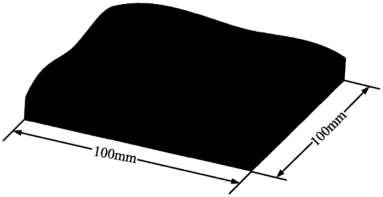
[0047] The effectiveness of the tool axis optimization method of the proposed curved surface CNC machining ball nose cutter wear control is verified below for the present invention in conjunction with the accompanying drawings, and relevant examples have been designed for verification. The constructed curved surface is as follows figure 1 shown. The material used for the workpiece is a nickel-based superalloy. Other parameters in the experiment are as follows:

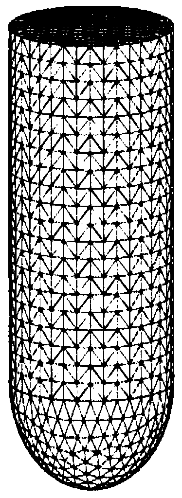
[0048] Tool: Ball-end knife, radius R12mm, 4 blades

[0049] depth of cut d c : 0.3mrn

[0050] Spindle speed N: 700rpm

[0051] Feed per tooth F z : 0.3mrn

[0052] Processing method: down milling

[0053] Tool wear threshold: 0.2mrn

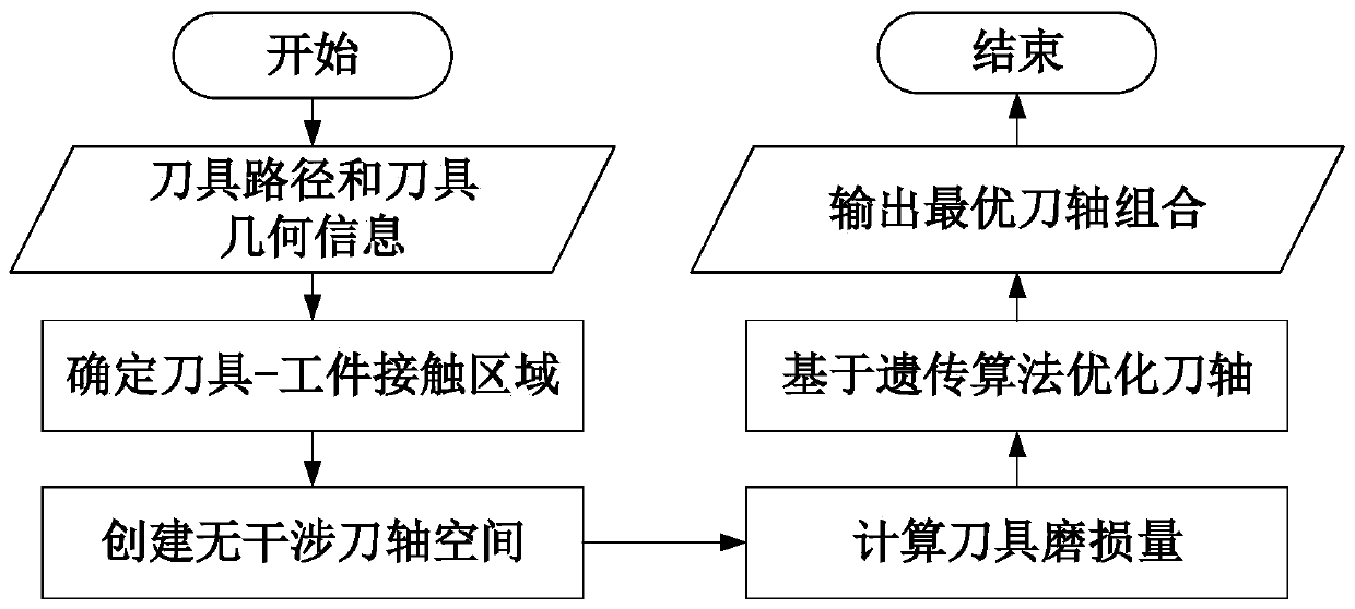
[0054] A tool axis optimization method for wear control of ball end milling cutters in NC machining of curved surfaces, such as figure 2 shown, including the following steps:

[0055] 1) Calculate the tool-workpiece engagement area at all tool positions. Extract the generate...


PUM


Abstract

The invention provides a cutter shaft optimization method for curved surface numerical control machining ball-end milling cutter abrasion control. The method comprises the following steps: firstly, constructing a cutter-workpiece meshing area at each cutter location point according to an input cutter path and geometrical information, and calculating an interference-free cutter shaft space at eachcutter location point; dividing the cutting edge of the cutter into a plurality of cutting intervals along the axial direction of the cutter; calculating the cutting length of each cutting interval ofthe cutter at each cutter location point under an initial cutter shaft according to the obtained cutter-workpiece meshing area to obtain the cutting length of the whole part machined by each cuttinginterval of the cutter edge, and calculating cutter abrasion loss of each cutting interval according to the abrasion rate; and finally, by adopting a fixed cutter shaft strategy, calculating cutter shaft direction in which the cutter abrasion is uniformly distributed in each cutting interval of the cutting edge from the non-interference cutter shaft space of each cutter location point. The methodis high in practicability and operability; and cutter abrasion is evenly distributed by adjusting the cutter shaft, and the problem that the cutter loses efficacy too fast due to the fact that the cutter abrasion is concentrated in a local area can be effectively solved.

Description

technical field [0001] The invention relates to a CAD / CAM technology, in particular to a multi-axis numerical control machining technology for free-form surfaces, in particular to a tool axis optimization method for wear control of ball-end milling cutters in numerical control machining of curved surfaces. Background technique [0002] A large number of difficult-to-machine materials such as titanium alloys and nickel-based superalloys are used in high-end equipment such as aviation, aerospace, and ships. The parts using such materials are easily worn during the processing process, which not only increases the manufacturing cost, but also seriously affects the final quality of the parts. Surface Quality. In addition, parts such as aero-engine blisks and casings usually have complex structures and curved surfaces, and NC programming is difficult. In order to save process preparation time in actual production, small-sized ball-end cutters are usually used for fixed-axis millin...

Claims


Application Information

Patent Timeline
IPC IPC(8): G05B19/19
CPCG05B19/19G05B2219/35349
Inventor 刘旭周宇周南沈泽东
Owner NANJING UNIV OF TECH
Why Eureka
Try Eureka