Heat dissipation device for power equipment

A technology for power equipment and cooling devices, which is applied in the cooling/ventilation direction of substations/switching devices, can solve problems such as power grid accidents, power grid paralysis, fires, etc., and achieve the effect of saving water resources and achieving good results.

Inactive Publication Date: 2020-03-17
李裕谋
View PDF7 Cites 6 Cited by
  • Summary
  • Abstract
  • Description
  • Claims
  • Application Information

AI Technical Summary

Problems solved by technology

[0002] Power equipment mainly includes power generation equipment and power supply equipment. Power generation equipment is mainly power plant boilers, steam turbines, gas turbines, water turbines, generators, transformers, etc. Power supply equipment is mainly transmission lines of various voltage levels, transformers, contactors etc. Power equipment in normal operation will generate heat due to the effect of current and voltage. When there is a defect or fault in the power equipment, the temperature of the defect or fault part will produce abnormal changes, which will cause local heating. Or the cooling of the entire power equipment will cause accidents such as fires, and even cause grid accidents and paralyze the grid.
Therefore, it is necessary to dissipate heat from some power equipment that is prone to heat. Traditional power equipment cooling devices use fans to dissipate heat from power equipment, and the heat dissipation effect is poor.

Method used


Image

  • Heat dissipation device for power equipment
  • Heat dissipation device for power equipment
  • Heat dissipation device for power equipment

Examples


Embodiment 1

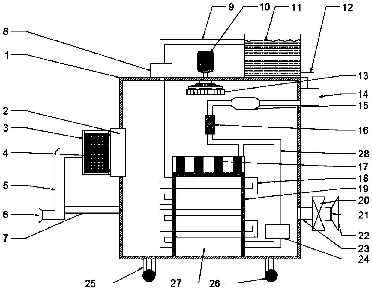
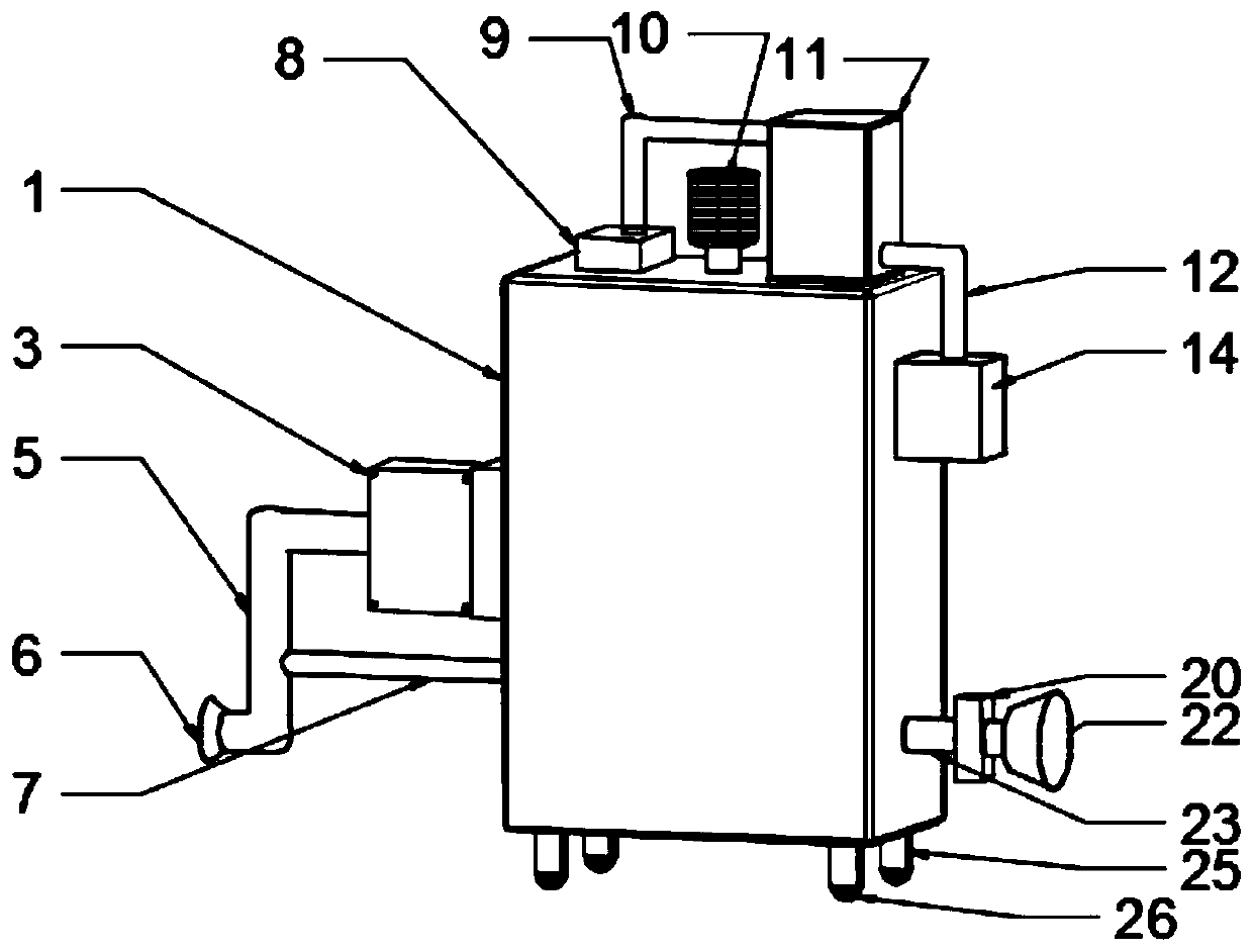
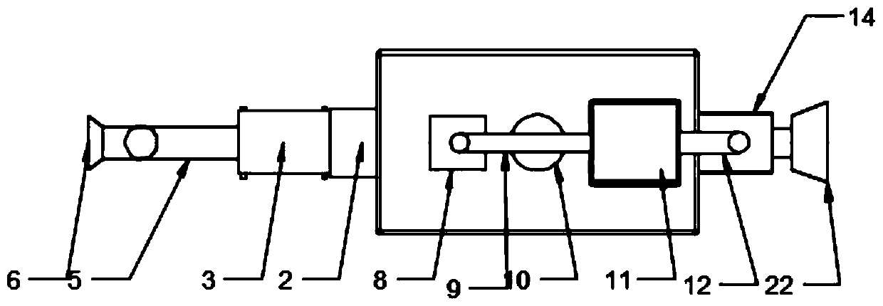
[0019] see Figure 1-3 , a heat dissipation device for electric power equipment, comprising a heat dissipation box 1, a water tank 11 is installed on the top right side of the heat dissipation box 1, the water tank 11 is connected to the top surface of the heat dissipation box 1 by bolts, and the right side wall of the water tank 11 is connected to a water outlet pipe 12 , the lower end of the water outlet pipe 12 is connected to a pressure water pump 14, and the pressure water pump 14 is connected to the right side surface of the cooling tank 1 by welding, and the pressure water pump 14 can make the pressure of the water extracted from the water tank 11 higher to ensure water circulation. The pressure water pump 14 is connected to the gasification pipe 15 through the water outlet pipe 12, and water can be vaporized in the gasification pipe 15 to absorb more heat. The gasification pipe 15 is connected to the liquefaction device 16 through the water outlet pipe 12, and the gaseo...

Embodiment 2

[0023] Such as Figure 1-3 , on the basis of embodiment 1, in order to exchange the cold and hot air in the heat dissipation box 1, the hot air is discharged, the cold wind is sucked into the heat dissipation box 1, and the air temperature in the heat dissipation box 1 is reduced. The air duct 23 is installed on the surface of the side wall, and the air duct 23 communicates with the inside of the cooling box 1. The right side of the air duct 23 is connected to the suction fan 20, and the right side of the suction fan 20 is equipped with a wind cover 22. The dust filter 21 is installed, the external cold air can be sucked into the cooling box 1 by the suction fan 20, the suction cover 22 can increase the air suction, and the dust filter 21 can filter out the dust in the air, so as not to affect the power of the electric equipment 27 In normal operation, the air cooling device 2 is installed on the left side wall of the heat dissipation box 1, and the wind cooling device 2 can c...


PUM


Abstract

The invention discloses a heat dissipation device for power equipment, and relates to the technical field of power equipment. The heat dissipation device comprises a heat dissipation box, a water tankis mounted at the top of the heat dissipation tank and is connected with a water outlet pipe, and the water outlet pipe is connected with a pressure water pump. The pressure water pump is connected with a gasification pipe, the gasification pipe is connected with a liquefaction device, and the liquefying device is connected with a branch pipeline. The branch pipeline is connected with a refrigerator, the refrigerator is connected with an annular water pipe, and the annular water pipe is connected with a water return pipe. The water return pipe is connected with a water supply pump, the watersupply pump is connected with the water tank, a suction fan is mounted on the surface of the right side wall of the heat dissipation box, and an air cooling device is mounted on the left side wall ofthe heat dissipation box. The water tank, the water outlet pipe, the pressure water pump, the annular water pipe, the water supply pump and the water return pipe are arranged to form a water circulation system, and the suction fan, an air exhaust adjusting box and the fan are arranged to form an air circulation system, so that the air in the heat dissipation box can fully flow. Through the mutual combination of the water circulation and the air circulation, the power equipment in the heat dissipation box are cooled.

Description

technical field [0001] The invention relates to the technical field of electric equipment, in particular to a cooling device for electric equipment. Background technique [0002] Power equipment mainly includes power generation equipment and power supply equipment. Power generation equipment is mainly power plant boilers, steam turbines, gas turbines, water turbines, generators, transformers, etc. Power supply equipment is mainly transmission lines of various voltage levels, transformers, contactors etc. Power equipment in normal operation will generate heat due to the effect of current and voltage. When there is a defect or fault in the power equipment, the temperature of the defect or fault part will produce abnormal changes, which will cause local heating. Or the cooling of the entire power equipment will cause accidents such as fires, and even cause grid accidents and paralyze the grid. Therefore, it is necessary to dissipate heat from some power equipment that is prone...

Claims


Application Information

Patent Timeline
Patent Type & Authority Applications(China)
IPC IPC(8): H02B1/56
CPCH02B1/56
Inventor 李裕谋
Owner 李裕谋
Why Eureka
Try Eureka