Cutter device of decorative plate production line

A technology for decorative panels and production lines, which is applied in auxiliary devices, welding/cutting auxiliary equipment, welding/welding/cutting items, etc. shift effect

Inactive Publication Date: 2020-03-24
广东澳林板业有限公司
View PDF1 Cites 10 Cited by
  • Summary
  • Abstract
  • Description
  • Claims
  • Application Information

AI Technical Summary

Problems solved by technology

[0003] The purpose of the present invention is to provide a cutter device for a decorative plate production line, which has the advantages of guiding the plate during conveying and pre-fixing during cutting, and solves the problem that the existing equipment does not have guidance when conveying plates and cannot be pre-fixed when breaking The problem

Method used


Image

  • Cutter device of decorative plate production line
  • Cutter device of decorative plate production line
  • Cutter device of decorative plate production line

Examples


Embodiment

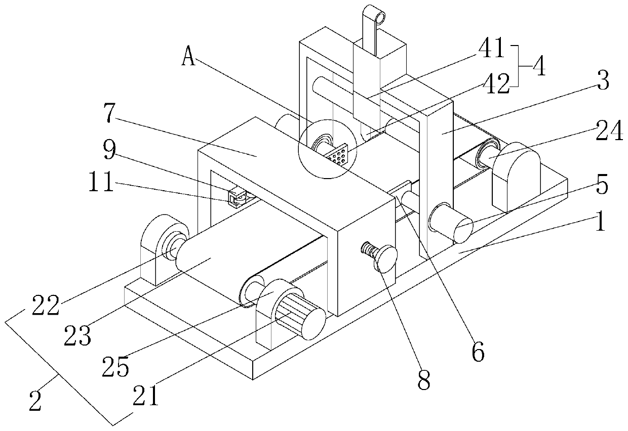
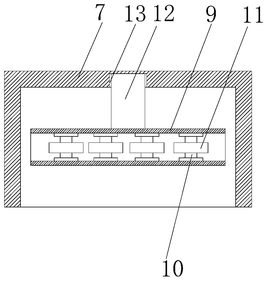
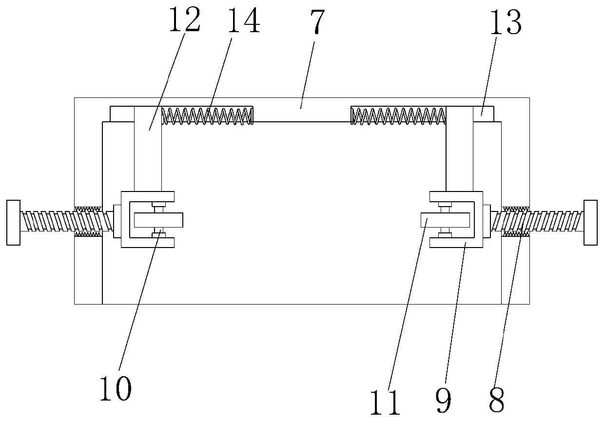
[0021] see Figure 1-4 , the cutter device of the decorative plate production line, including a support base 1, the top of the support base 1 is provided with a conveying assembly 2, the right side of the top of the support base 1 is welded with a gantry 3, and the top of the inner cavity of the gantry 3 is fixed with a laser cutting The knife machine 4 and the bottoms of the front and rear sides of the gantry 3 are fixedly connected with an electric cylinder 5, the telescopic end of the electric cylinder 5 runs through the gantry 3 and extends to the inner cavity of the gantry 3, and the telescopic end of the electric cylinder 5 is welded with a splint 6 , the top of the support base 1 and the left side of the gantry 3 are welded with a support frame 7, the front and rear sides of the support frame 7 are threaded with threaded rods 8, and the opposite side of the threaded rods 8 runs through the support frame 7 and extends to The inner cavity of the support frame 7, the oppos...


PUM


Abstract

The invention discloses a cutter device of a decorative plate production line, which comprises a supporting base. A conveying assembly is arranged at the top of the supporting base. A portal frame iswelded to the right side of the top of the supporting base, a laser cutter is fixedly arranged at the top of an inner cavity of the portal frame, electric air cylinders are fixedly connected to the bottoms of the front side and the rear side of the portal frame, and the telescopic ends of the electric air cylinders penetrate through the portal frame and extend into the inner cavity of the portal frame. The conveying assembly is arranged for conveying the plate, the electric air cylinder is arranged to drive the clamping plate to move, the plate is fixed in advance when being broken, a threadedrod is arranged to rotate in the supporting frame, a slider slides in the sliding groove, the distance between the opposite views of the guide wheels is adjusted, meanwhile, the guide effect is achieved, the problems that existing equipment does not have the guide function during plate conveying and cannot be pre-fixed during breaking are solved, therefore, plates are not prone to deviating, andthe breaking accuracy is improved.

Description

technical field [0001] The invention relates to the technical field of decorative plate cutting, in particular to a cutter device for a decorative plate production line. Background technique [0002] Decorative board is a kind of man-made board. It is a thermosetting laminated plastic made of high-temperature and high-pressure adhesive after chemical treatment with a variety of special papers. The board surface has various wood grains or patterns, bright and flat, bright and beautiful. At the same time, it has good physical properties such as high wear resistance, heat resistance, cold resistance, and fire prevention. In the continuous automatic production process of decorative panels, it is necessary to pre-cut the continuous strip-shaped decorative panels in a wet state. Patent No. CN207642401U provides a cutter device for a decorative board production line. Although the laser cutter device is used to cut the board in this patent, it does not have a guiding effect on the b...

Claims


Application Information

Patent Timeline
Patent Type & Authority Applications(China)
IPC IPC(8): B23K26/38B23K26/402B23K26/08B23K37/04B23K101/18
CPCB23K26/0838B23K26/38B23K26/402B23K37/0408B23K2101/18B23K2103/42
Inventor 陆纪互
Owner 广东澳林板业有限公司
Why Eureka
Try Eureka