


Quick Research
Generate reliable direction feasibility study reports for your R&D in just a few steps.

Technical Q&A
Discover and master advanced knowledge NOW. Basics, ideas, possibilities, all at once.

Find Solutions
As an expert in R&D theories, this can generate solutions to your technical problems instantly.

Evaluate Feasibility
Analyze your overall solution with one click, know your potential R&D risks in advance.

Monitor Landscape
Get weekly tech updates, stay abreast of the latest tech innovations and key insights.
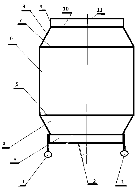
Flying saucer
A technology of flying saucer and saucer frame, applied in the field of flying saucer, can solve the problems of complex structure of air supply device, poor stability of aircraft, increase of aircraft manufacturing cost and self-weight, etc.
- Summary
- Abstract
- Description
- Claims
- Application Information
AI Technical Summary
Problems solved by technology
Method used
Image

Examples
Embodiment Construction
[0024]The object of the present invention is achieved in that when the flying saucer takes off, first the flying spray nozzle in the bottom rotating cylinder is pushed out outwards, and the take-off nozzle is adjusted under the fixed jet valve of the engine to make it hermetically connected. Then start the driving motor on the bottom surface of the flying saucer, the driving motor drives the rotary air supply valve of the engine to rotate, and at the same time drives the air supply acceleration device in the central shaft below to start working, connecting the top plane with the circular air supply pipe to increase the intake air The supply pressure of the device through the longitudinal air supply pipe ... the control valve ... enters the pressurized air storage tank below. When the rotary air supply valve speed of the engine reaches 3000 rpm, the air supply and oil supply devices of the engine start to work, and then the take-off nozzle starts to spray air downward. At the s...
PUM
 Abstract
Description
Claims
Application Information
 - R&D Engineer
- R&D Manager
- IP Professional
- Industry Leading Data Capabilities
- Powerful AI technology
- Patent DNA Extraction
Browse by: Latest US Patents, China's latest patents, Technical Efficacy Thesaurus, Application Domain, Technology Topic, Popular Technical Reports.
© 2024 PatSnap. All rights reserved.Legal|Privacy policy|Modern Slavery Act Transparency Statement|Sitemap|About US| Contact US: help@patsnap.com