

A method for testing the strength of helicopter blades
A strength test and helicopter technology, applied in the field of rotor strength test, to avoid test calibration and debugging work, improve test accuracy, and achieve great technological progress
Active Publication Date: 2022-06-03
CHINA HELICOPTER RES & DEV INST
View PDF13 Cites 0 Cited by
- Summary
- Abstract
- Description
- Claims
- Application Information
AI Technical Summary
Problems solved by technology
[0004] The improved current blade test method has a major assumption that the strain-load curve increases linearly during the entire life cycle of the blade from the beginning to the failure of tensile bending
Method used
View moreImage
Smart ImageViewing Examples

Examples
Embodiment Construction
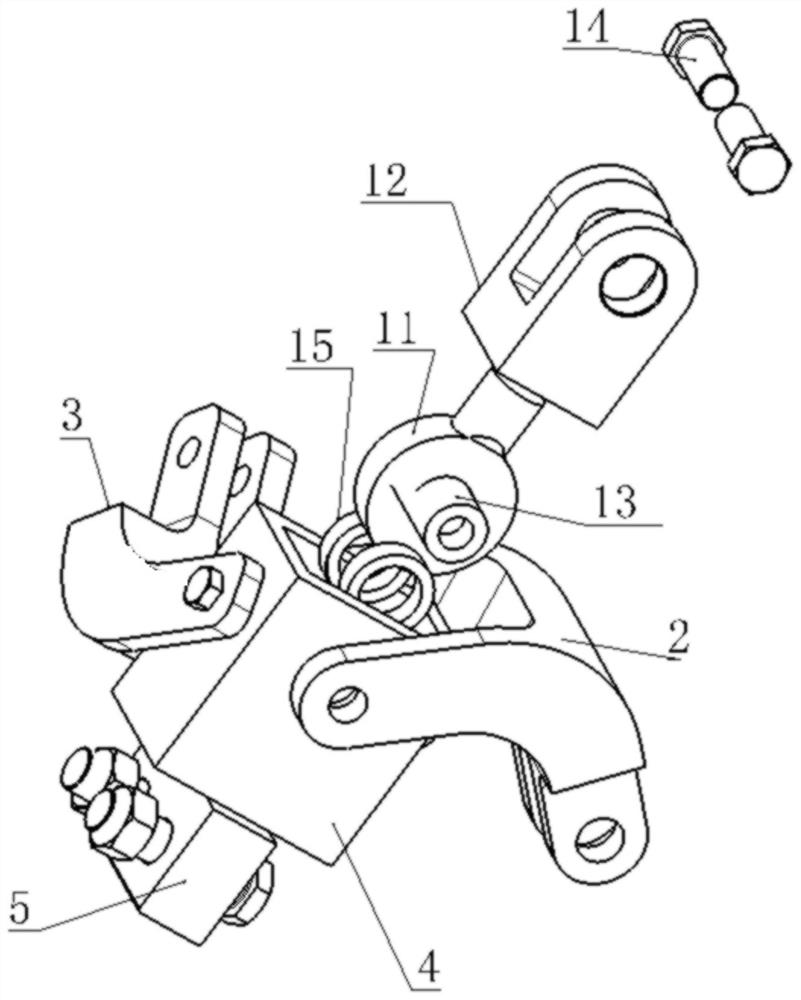
[0038] In addition, the loading connection fork lug 12 is vertically connected with the shank spherical plain bearing 11 to provide centrifugal force loading.
Login to View More PUM
 Abstract
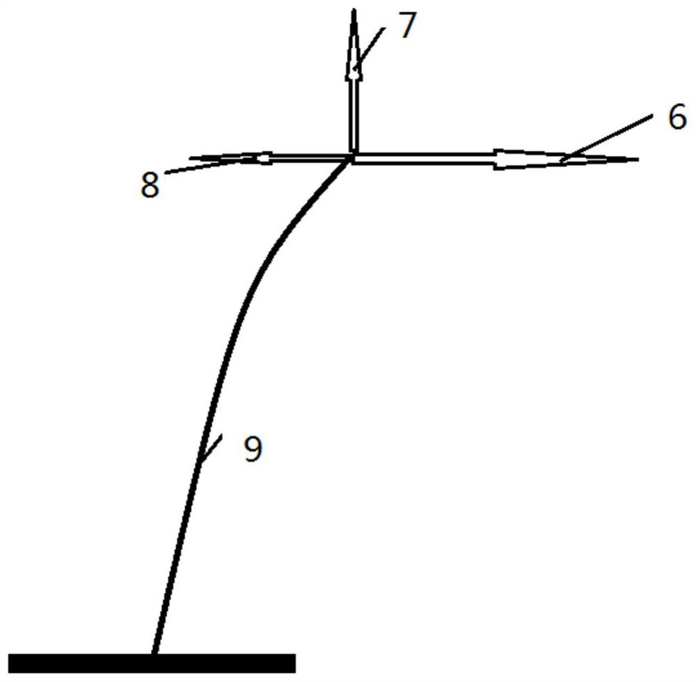
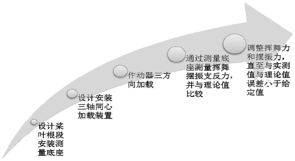
The invention belongs to the field of rotor strength testing and relates to a helicopter blade strength testing method. When the helicopter blade strength test method of the present invention is loaded, the F centrifugal force is applied in the direction of the centrifugal force of the blade, and the F waving force is applied in the waving direction of the blade at the same time, and the F waving force is adjusted by monitoring the magnitude of the support reaction force F0 in the waving direction of the fixed end of the blade root. Force, so that the waving direction support reaction force F0 reaches the theoretical waving load value. The shimmy direction is the same as the swinging direction. The helicopter blade strength test method of the present invention avoids the assumption of linear change of load and strain in the whole life cycle of the structure, and by changing the indirect measurement to direct load control, the cumbersome test calibration and debugging work is effectively avoided, the labor intensity is reduced, and the test efficiency is improved. Simplicity, while avoiding the risk of out-of-control load loading during the destruction process of the test piece by the indirect control method, and providing analysis data for the load-strain relationship of the test piece throughout the life cycle, which can effectively improve the efficiency and accuracy of the static strength test of the blade.
Description
A kind of helicopter blade strength test method technical field The invention belongs to rotor strength test field, relate to a kind of helicopter blade strength test method. Background technique Helicopter strength design is one of the important contents of helicopter development work, and its goal is to meet the needs of strong Under the premise of the requirements of the minimum weight, the optimal scheme to ensure the structural strength is selected and determined. The rotor blades are straight The main source of lift of an elevator, its strength and performance are related to the performance and safety of the entire rotor system, and even the whole aircraft. The blade moves periodically, and the aerodynamic load acting on each section of the blade also varies with the azimuth angle and section position of the blade. At the same time, the force condition of the rotor blade is particularly complicated. Therefore, it is necessary to carry out a strict static stre...
Claims
Login to View More Application Information
Patent Timeline
 Patent Type & AuthorityPatents(China)
IPC IPC(8): B64F5/60B64C27/46
CPCB64F5/60B64C27/46Y02T90/00
Inventor唐江光杨丛青
OwnerCHINA HELICOPTER RES & DEV INST